
Voltage converter for implantable microstimulator using RF-powering coil

a microstimulator and voltage converter technology, applied in electrotherapy, therapy, etc., can solve the problems of large volume of capacitors, inconvenient operation of charge pump circuits that use large numbers of bulky capacitors, and inability to meet the needs of implantable medical devices, etc., to achieve a wide range of output voltage and current.

Inactive Publication Date: 2005-06-16
BOSTON SCI NEUROMODULATION CORP
View PDF11 Cites 33 Cited by
  • Summary
  • Abstract
  • Description
  • Claims
  • Application Information

AI Technical Summary

Benefits of technology

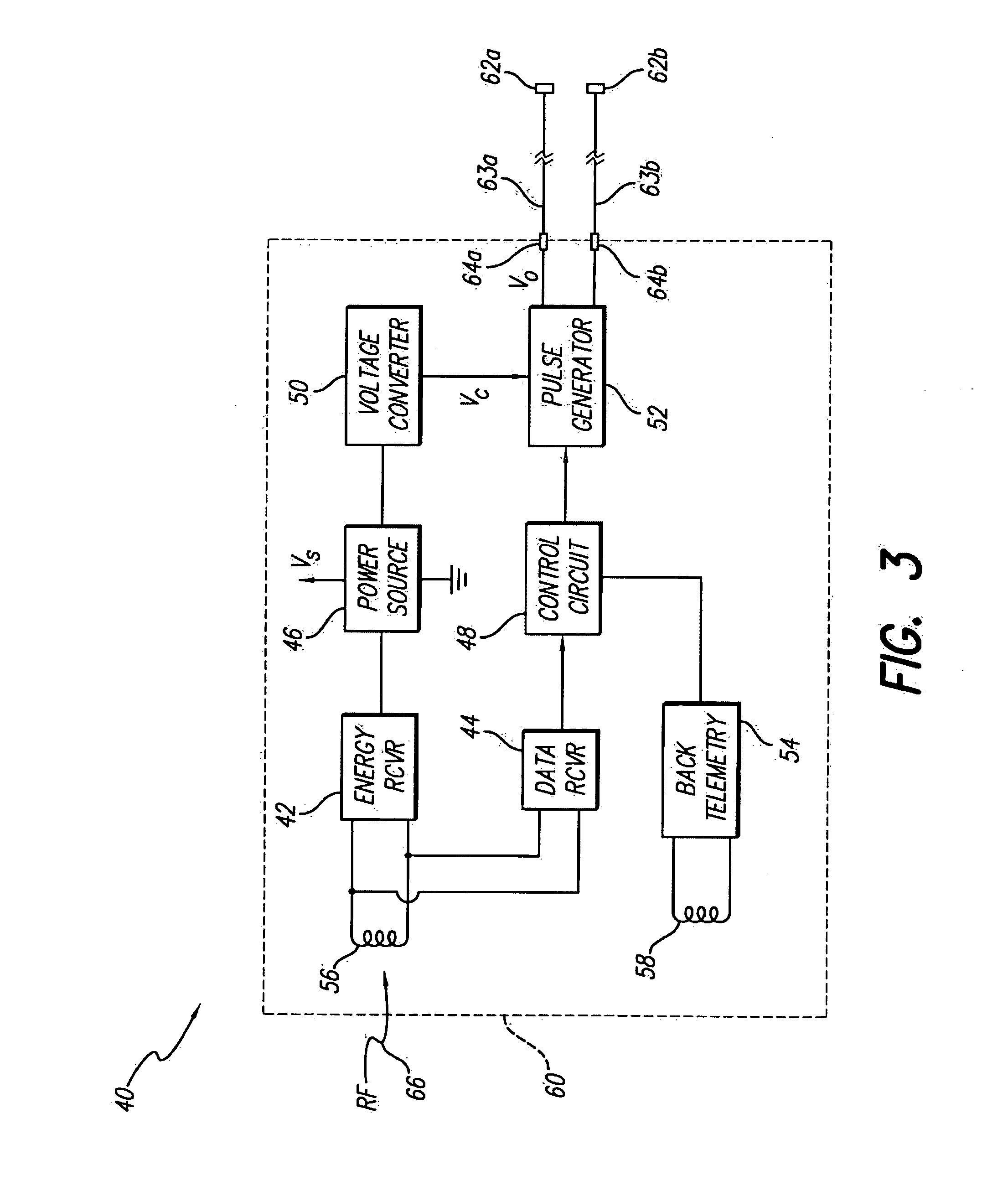
[0007] In accordance with one aspect of the invention, applicable to implantable devices having an existing RF coil through which primary or charging power is provided, the existing RF coil is used in a time-multiplexing scheme to provide both the receipt of the RF signal and the voltage conversion function. This minimizes the number of components needed within the device, and thus allows the device to be packaged in a smaller housing, or frees up additional space within an existing housing for other circuit components. The result is an implantable device having a voltage converter that may be much smaller and / or more densely packed than prior implantable devices.
[0008] In accordance with another aspect of the invention, the voltage up / down converter circuit is controlled by a pulse width modulation (PWM) and / or ON / OFF modulation (OOM) low power control circuit. Such operation advantageously allows high efficiencies over a wide range of output voltages and current loads.
[0010] It is thus a feature of the present invention to provide a voltage converter circuit for use within an implantable device, e.g., such as an implantable microstimulator or similar type of neural stimulator, that is compact, efficient, and provides a wide range of output voltages and currents.
[0011] It is a further feature of the invention to provide a voltage converter circuit that avoids the use of a network of capacitors switched between parallel and series, or other, configurations in order to provide the step up and step down voltage conversion function.

Problems solved by technology

While charge-pump circuits have proven effective for performing step up and step down functions, such circuits require a large number of capacitors, which capacitors may be quite large and bulky.
Charge pump circuits that use large numbers of bulky capacitors are not well suited for implantable medical devices that must remain very small.
Moreover, charge pump circuits tend to be relatively slow and inefficient in operation.

Method used


Image

  • Voltage converter for implantable microstimulator using RF-powering coil
  • Voltage converter for implantable microstimulator using RF-powering coil
  • Voltage converter for implantable microstimulator using RF-powering coil

Examples


Embodiment Construction

[0022] The following description is of the best mode presently contemplated for carrying out the invention. This description is not to be taken in a limiting sense, but is made merely for the purpose of describing the general principles of the invention. The scope of the invention should be determined with reference to the claims.

[0023] The present invention relates to a particular type of voltage converter that may be used within an implantable medical device, such as an implantable stimulator, sensor, pump or other type of medical device providing a desired medical function. The invention will be described below in terms of an implantable stimulator, but it is to be understood that the invention may be used within many different types of implantable devices.

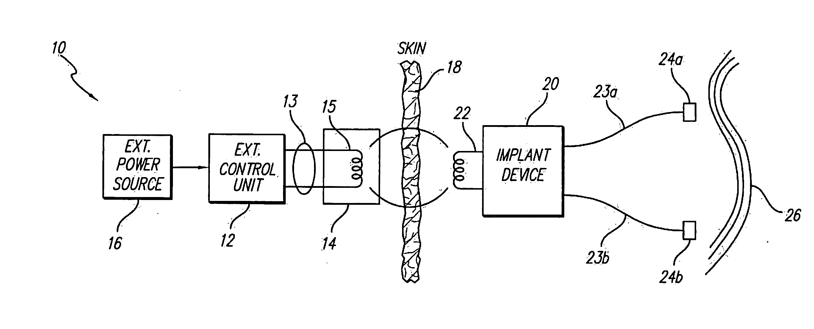
[0024] To better understand the environment in which the invention is intended to be used, it will first be helpful to review a typical implantable stimulation system. Hence, with reference to FIG. 1, a block diagram of a rep...


PUM


Abstract

A combination, voltage converter circuit for use within an implantable device, such as a microstimulator, uses a coil, instead of capacitors, to provide a voltage step up and step down conversion functions. The output voltage is controlled, or adjusted, through duty-cycle modulation. In accordance with one aspect of the invention, applicable to implantable devices having an existing RF coil through which primary or charging power is provided, the existing RF coil is used in a time-multiplexing scheme to provide both the receipt of the RF signal and the voltage conversion function. This minimizes the number of components needed within the device, and thus allows the device to be packaged in a smaller housing or frees up additional space within an existing housing for other circuit components. In accordance with another aspect of the invention, the voltage up / down converter circuit is controlled by a pulse width modulation (PWM) low power control circuit. Such operation allows high efficiencies over a wide range of output voltages and current loads.

Description

[0001] The present application is a continuation application of U.S. application Ser. No. 09 / 799,467, filed Mar. 5, 2001, which application claims the benefit of Provisional Application Ser. No. 60 / 189,992, filed Mar. 17, 2000. Both applications are herein incorporated by reference in their entireties.BACKGROUND OF THE INVENTION [0002] The present invention relates to implantable medical devices, and more particularly to a voltage converter for use within an implantable microstimulator, or similar implantable device, that uses an RF-powering coil instead of capacitors to provide a voltage step-up and step-down function. [0003] Many implantable medical devices, such as neural stimulators, sensors, and the like, utilize a battery as a primary source of operating power. Other types of implantable devices, such as cochlear stimulators, rely on the presence of an alternating magnetic field to induce an ac voltage into the implantable device, where the induced voltage is thereafter rectif...

Claims


Application Information

Patent Timeline
Patent Type & Authority Applications(United States)
IPC IPC(8): A61N1/00A61N1/08
CPCA61N1/08A61N1/37205A61N1/3787
Inventor PARRAMON, JORDIHALLER, MATTHEW I.
Owner BOSTON SCI NEUROMODULATION CORP
Learn More