Method and arrangement for obtaining information about vehicle occupants

a technology for obtaining information and occupants, applied in vehicle seats, special data processing applications, headlamps, etc., can solve the problems of high cost of laser systems described above, inaccurate control of the area covered, and inability to meet the requirements of ccd or cmos arrays

Inactive Publication Date: 2005-06-16
AMERICAN VEHICULAR SCI
View PDF41 Cites 325 Cited by
  • Summary
  • Abstract
  • Description
  • Claims
  • Application Information

AI Technical Summary

Problems solved by technology

In this case, the area covered is not as accurately controlled and a larger CCD or CMOS array is required.
The laser systems described above are expensive due to the requirement that they be modulated at a high frequency if the distance from the airbag to the occupant, for example, is to be measured.
A single camera is, naturally, the least expensive solution but suffers from the problem that there is no easy method of obtaining three-dimensional information about people or objects in the passenger compartment.
A second camera can be added, but to locate the same objects or features in the two images by conventional methods is computationally intensive unless the two cameras are close together.
If they are close together, however, then the accuracy of the three dimensional information is compromised.
Since the LED illumination is now more expensive than the imager, the cost of the second camera does not add significantly to the system cost.
A mechanical focusing system, such as used on some camera systems, can determine the initial position of an occupant but is currently too slow to monitor his / her position during a crash or even during pre-crash braking.
Although the Subbarao patents provide a good discussion of the camera focusing art, it is a more complicated system than is needed for practicing the instant inventions.
This technology could provide input data to a pattern recognition system but it has limitations related to temperature.
The sensing of the child could pose a problem if the child is covered with blankets, depending on the IR frequency used.
It also might not be possible to differentiate between a rear facing child seat and a forward facing child seat.
In all cases, the technology can fail to detect the occupant if the ambient temperature reaches body temperature as it does in hot climates.
Prior art systems are mostly limited to single pixel devices.
Their main drawback is cost which is usually above that of ultrasonic or passive infrared systems.
It does not apply this technique for automotive applications and in particular for occupant sensing or monitoring inside or outside of a vehicle.
“Out-of-position” as used for an occupant will generally mean that the occupant, either the driver or a passenger, is sufficiently close to an occupant protection apparatus (airbag) prior to deployment that he or she is likely to be more seriously injured by the deployment event itself than by the accident.
It may also mean that the occupant is not positioned appropriately in order to attain the beneficial, restraining effects of the deployment of the airbag.
Thus, the state of the vehicle could be normal when the vehicle is operating properly on a highway or abnormal when, for example, the vehicle is experiencing excessive angular inclination (e.g., two wheels are off the ground and the vehicle is about to rollover), the vehicle is experiencing a crash, the vehicle is skidding, and other similar situations.

Method used


Image

  • Method and arrangement for obtaining information about vehicle occupants
  • Method and arrangement for obtaining information about vehicle occupants
  • Method and arrangement for obtaining information about vehicle occupants

Examples


Embodiment Construction

[0188] Note whenever a patent or literature is referred to below it is to be assumed that all of that patent or literature is to be incorporated by reference in its entirety to the extent the disclosure of these reference is necessary. Also note that although many of the examples below relate to a particular vehicle, an automobile, the invention is not limited to any particular vehicle and is thus applicable to all relevant vehicles including shipping containers and truck trailers and to all compartments of a vehicle including, for example, the passenger compartment and the trunk of an automobile or truck.

[0189] 1. General Occupant Sensors

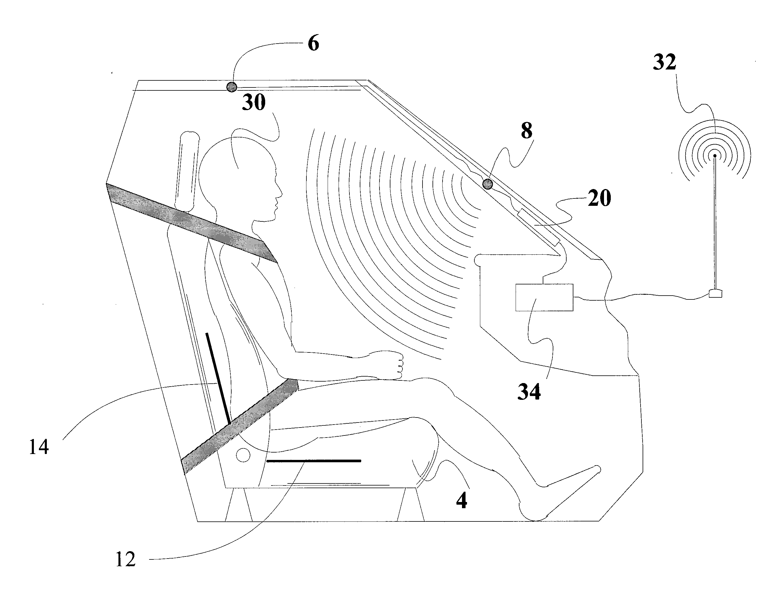
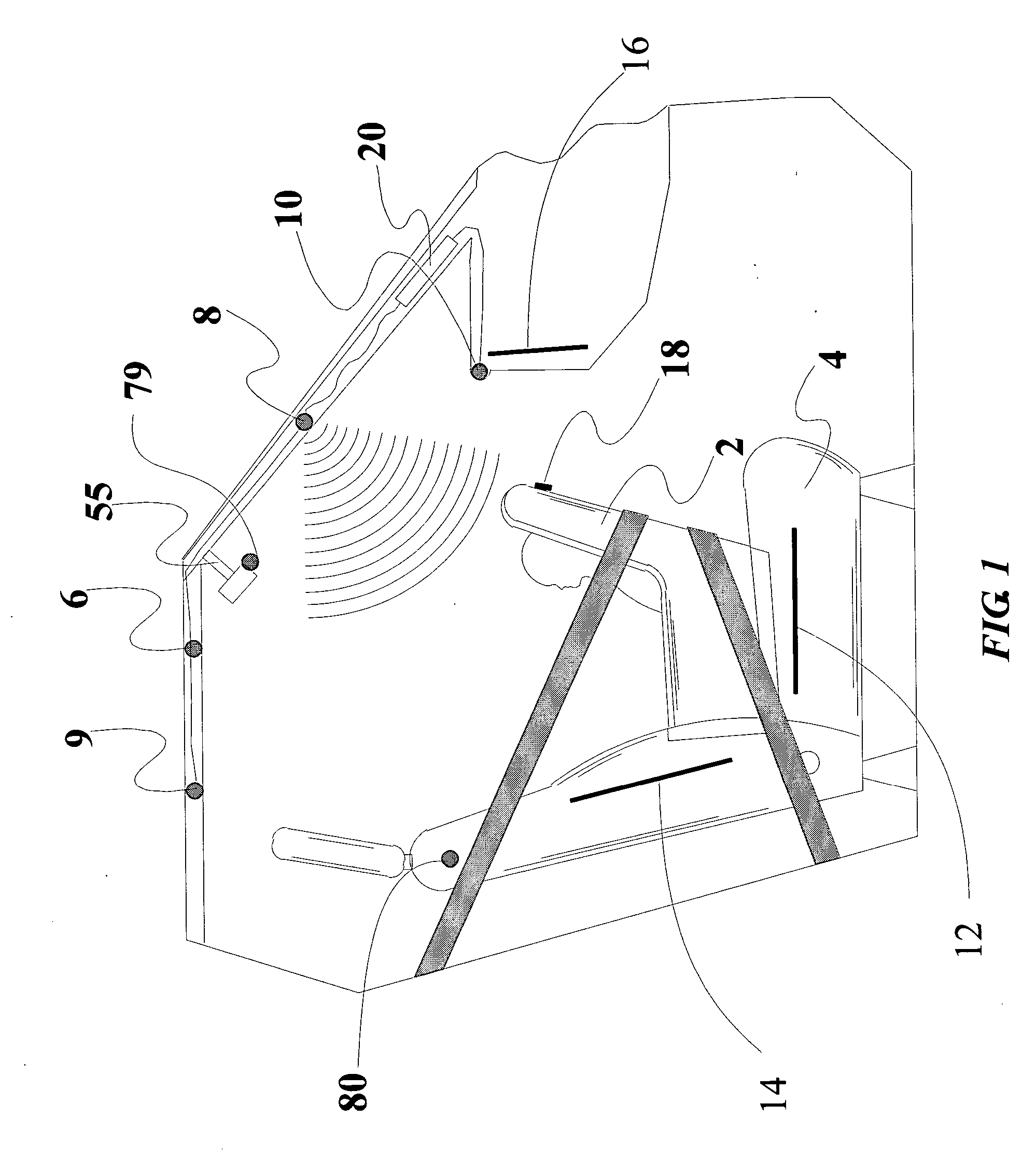
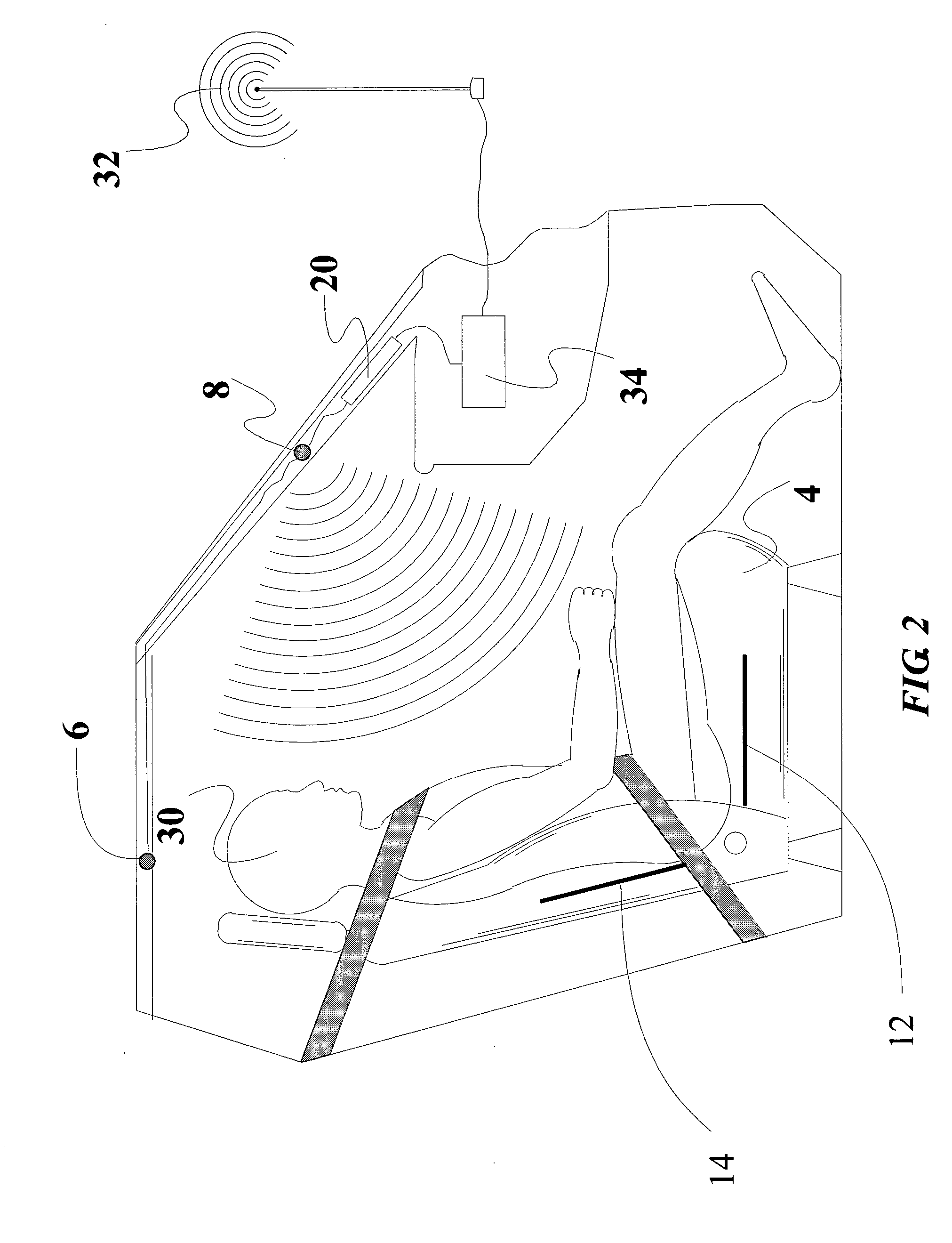
[0190] Referring to the accompanying drawings, FIG. 1 is a side view, with parts cutaway and removed of a vehicle showing the passenger compartment, or passenger container, containing a rear facing child seat 2 on a front passenger seat 4 and a preferred mounting location for a first embodiment of a vehicle interior monitoring system in accordanc...


PUM


Abstract

Arrangement and method for obtaining information about a vehicle occupant in a compartment of the vehicle in which a light source is mounted in the vehicle, structured light is projected into an area of interest in the compartment, rays of light forming the structured light originating from the light source, reflected light is detected at an image sensor at a position different than the position from which the structured light is projected, and the reflected light is analyzed relative to the projected structured light to obtain information about the area of interest. The structured light is designed to appear as if it comes from a source of light (virtual or actual) which is at a position different than the position of the image sensor.

Description

CROSS REFERENCE TO RELATED APPLICATIONS [0001] This application is: [0002] 1. a continuation-in-part of U.S. patent application Ser. No. 10 / 116,808 filed Apr. 5, 2002 which is: [0003] a. a continuation-in-part of U.S. patent application Ser. No. 09 / 838,919 filed Apr. 20, 2001, now U.S. Pat. No. 6,442,465, which is: [0004] 1) a continuation-in-part of U.S. patent application Ser. No. 09 / 765,559 filed Jan. 19, 2001, now U.S. Pat. No. 6,553,296, which is a continuation-in-part of U.S. patent application Ser. No. 09 / 476,255 filed Dec. 30, 1999, now U.S. Pat. No. 6,324,453, which claims priority under 35 U.S.C. §119(e) of U.S. provisional patent application Ser. No. 60 / 114,507 filed Dec. 31, 1998; and [0005] 2) a continuation-in-part of U.S. patent application Ser. No. 09 / 389,947 filed Sep. 3, 1999, now U.S. Pat. No. 6,393,133, which is a continuation-in-part of U.S. patent application Ser. No. 09 / 200,614, filed Nov. 30, 1998, now U.S. Pat. No. 6,141,432, which is a continuation of U.S. ...

Claims


Application Information

Patent Timeline
Patent Type & Authority Applications(United States)
IPC IPC(8): B60N2/00B60N2/02B60N2/28B60Q1/14B60R21/01B60R21/0134B60R21/015B60R22/20G01S15/87G01S15/88G01S17/88G06K9/00
CPCB60N2/002B60R21/0152B60N2/0244B60N2/0276B60N2/28B60N2/2806B60N2/2863B60N2002/0268B60Q1/143B60Q2300/41B60Q2300/42B60R21/013B60R21/0134B60R25/25B60R25/252B60R25/255B60R25/257B60R2022/208G01S15/87G01S15/88G01S17/88G06K9/00362G06K9/00832B60N2002/0272B60R21/01536B60R21/01534B60R21/01538B60N2/0232G06V40/10G06V20/59B60N2/0272B60N2/0268B60N2/02246
Inventor BREED, DAVID S.
Owner AMERICAN VEHICULAR SCI
Why Eureka
Try Eureka