Self cleaning filter and vacuum incorporating same

a self-cleaning and vacuum technology, applied in the field of vacuums, can solve the problems of reducing the strength of the vacuum, reducing the amount of air being drawn into the vacuum, and accumulating dust from the air stream passing through the vacuum, so as to reduce the load on the motor, slow the speed of brush rotation, and clean the filter of the vacuum.

Inactive Publication Date: 2005-06-23
YAU LAU KWOK
View PDF11 Cites 123 Cited by
  • Summary
  • Abstract
  • Description
  • Claims
  • Application Information

AI Technical Summary

Benefits of technology

[0009] It is still another object of the invention to clean the filter of a vacuum without substantially taxing the motor of the vacuum.
[0010] It is yet another object of the invention to clean the filter of a vacuum without substantially taxing the power source of the vacuum.
[0011] The invention comprises a brush configured to move repeatedly over the filter of a vacuum or other filtration device. The brush will remove dust particles to prevent them from clogging the filter. In the preferred embodiment, the brush is mounted on a revolving shaft. As the shaft turns it moves the bristles of the brush over the surface of the filter, whereby dust particles may be dislodged. In one embodiment, the shaft is attached to the vacuum motor and is turned directly by the motor. In this embodiment a speed reducer may be employed to slow the rate of rotation of the brush. In another embodiment, a turbine is attached to the shaft. The turbine is placed in the path of the air stream moving through the vacuum. The air passing through the turbine causes it and the shaft to rotate, thereby reducing the load on the motor.

Problems solved by technology

With use, dust from the air stream passing through the vacuum tends to build up in the prior art filters.
This diminishes the amount of air being drawn into the vacuum which in turn diminishes the strength of the vacuum.
Thus, prior art vacuums steadily lose strength over the life of their filters.
Eventually, the filters become so clogged that they must be removed and either replaced or cleaned.

Method used


Image

  • Self cleaning filter and vacuum incorporating same
  • Self cleaning filter and vacuum incorporating same
  • Self cleaning filter and vacuum incorporating same

Examples


Embodiment Construction

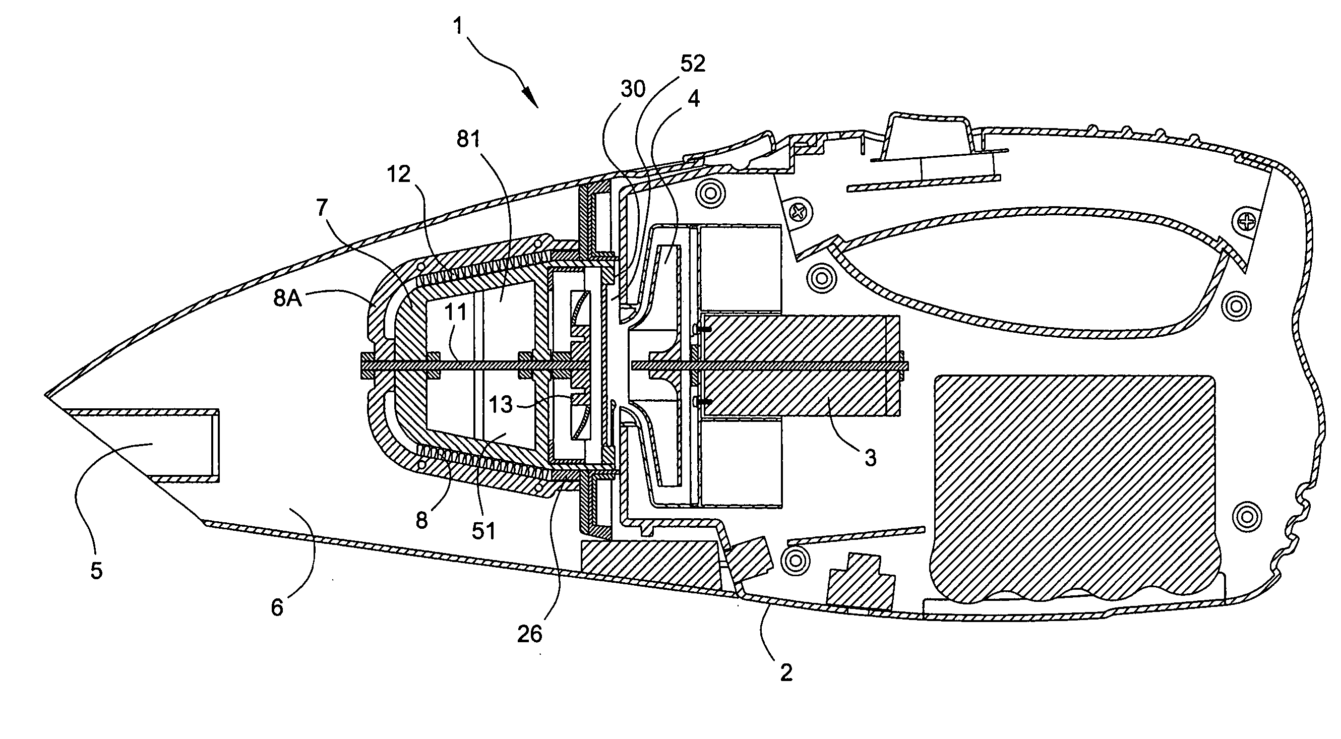
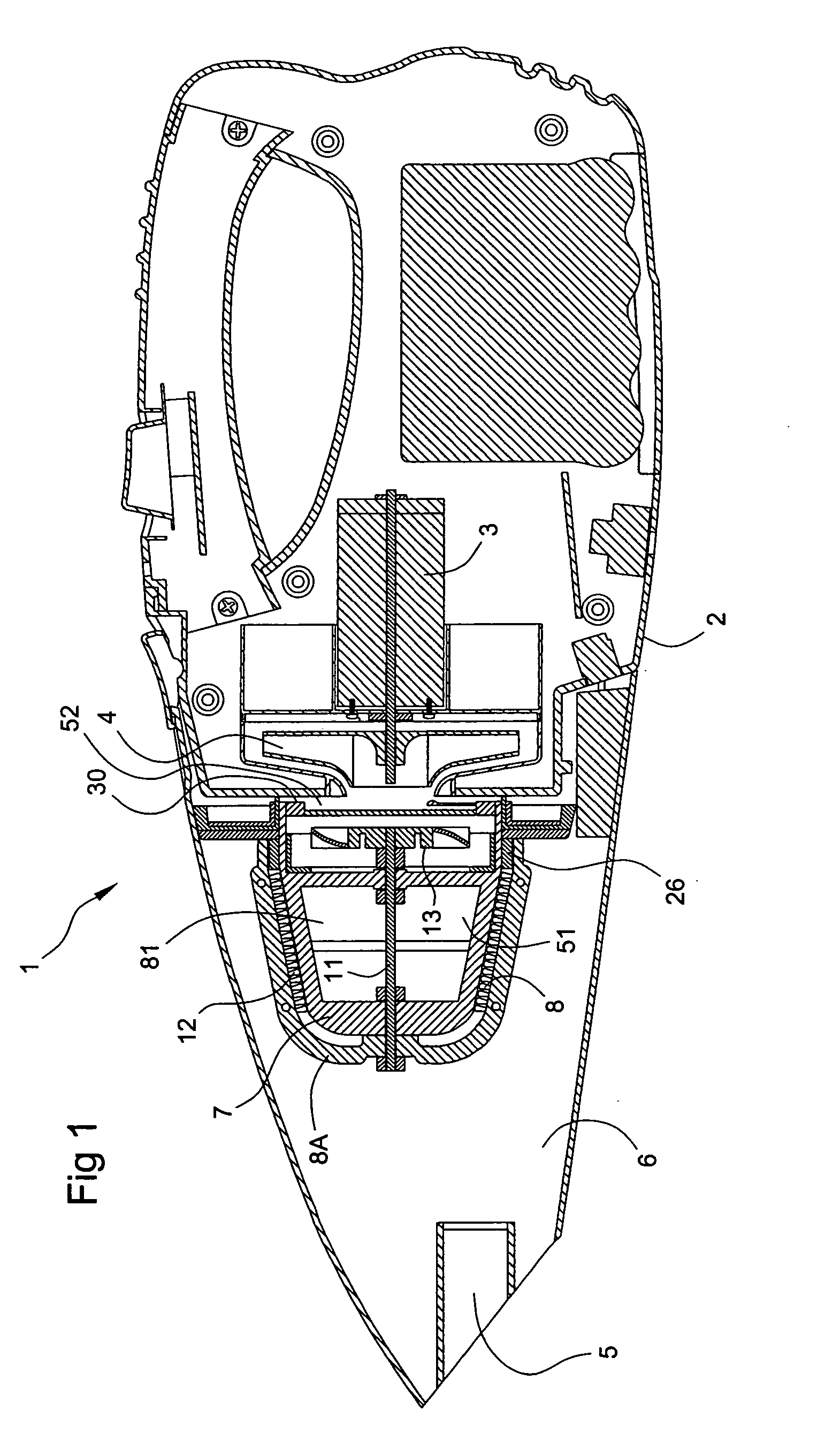
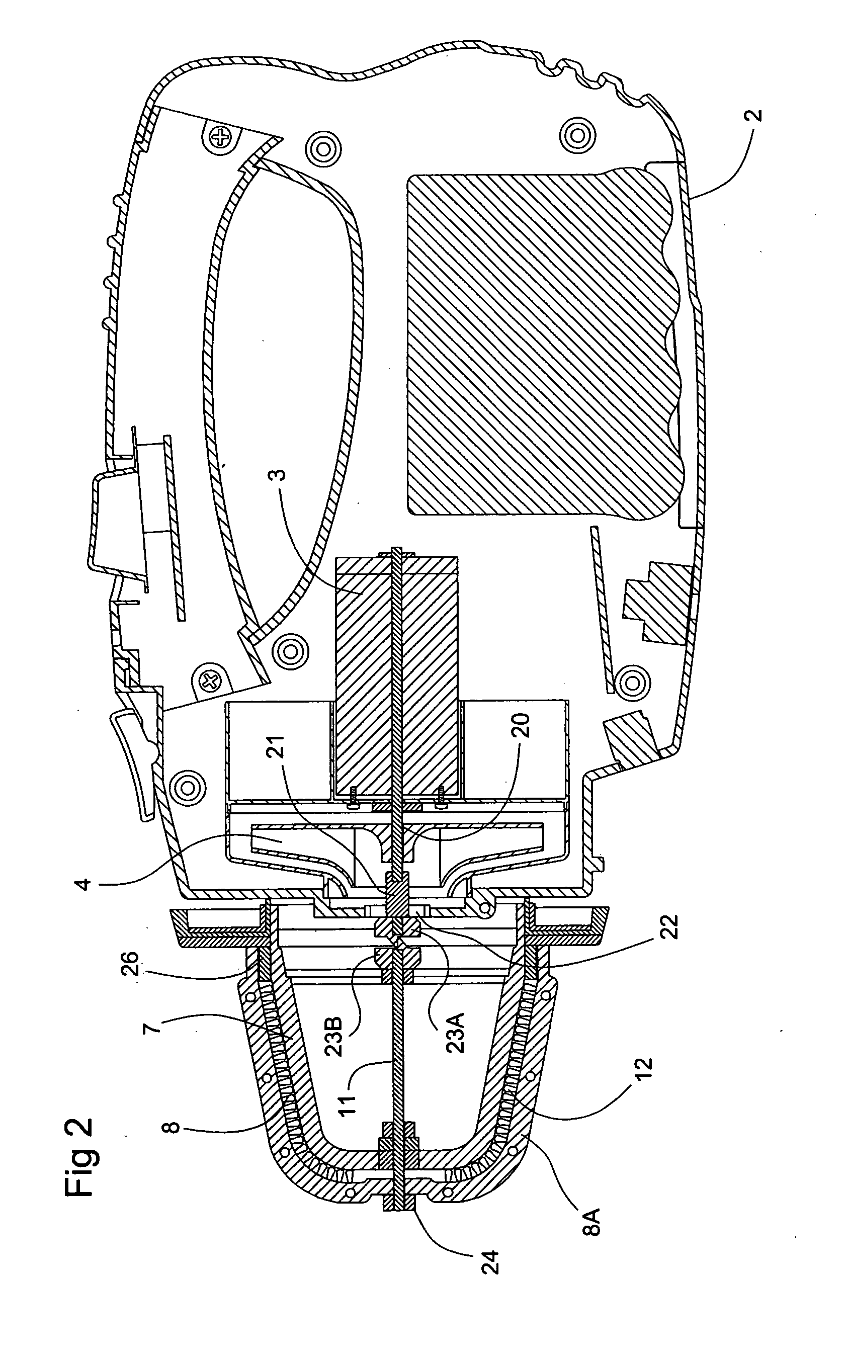
[0023] One embodiment of the invention comprises an improvement to a vacuum 1. Most vacuums 1 comprise a housing 2 containing a motor 3, typically electric, which drives a fan 4. Fan 4 pulls air through an inlet 5 or other orifice and into a dust collection chamber 6. Dust collection chamber 6 may be integral with housing 2 or it may be in a separate structure. In the preferred embodiment, dust collection chamber 6 is a rigid container, but it may also be a pliable container, as in the case of disposable vacuum bags, or any other conventional vacuum dust collector.

[0024] As air is drawn into inlet 5 and dust collection chamber 6 from outside vacuum 1, it picks up dust and other refuse and brings them into vacuum 1. The air exits dust collection chamber 6 through an outlet 51. Outlet 51 should communicate with an intake aperture 52 leading to fan 4. Intake aperture 52 may be in housing 2 and it may be the same aperture as outlet 51. The important thing is that outlet 51 and fan 4 be...


PUM

PropertyMeasurementUnit
speedaaaaaaaaaa
strengthaaaaaaaaaa
vacuumaaaaaaaaaa

Abstract

A brush configured to move repeatedly over a vacuum filter. The brush will remove dust particles to prevent them from clogging the filter. In the preferred embodiment, the brush is mounted on a revolving shaft. As the shaft turns it moves the bristles of the brush over the surface of the filter, whereby dust particles may be dislodged. In one embodiment, the shaft is attached to the vacuum motor and is turned directly by the motor. In this embodiment a speed reducer may be employed to slow the rate of rotation of the brush. In another embodiment, a turbine is attached to the shaft. The turbine is placed in the path of the air stream moving through the vacuum. The air passing through the turbine cause it and the shaft to rotate, thereby reducing the load on the motor.

Description

BACKGROUND OF THE INVENTION [0001] 1. Field of the Invention [0002] The invention relates to vacuums in general and vacuums containing filters in particular. [0003] 2. Prior Art [0004] Vacuum filters screen the flow of air through the vacuum. Dirty dust laden air is kept on one side of the filter, while clean air passes through to the fan and is discharged from the vacuum. With use, dust from the air stream passing through the vacuum tends to build up in the prior art filters. As the filters become more clogged, less and less air can be pulled through the filter. This diminishes the amount of air being drawn into the vacuum which in turn diminishes the strength of the vacuum. Thus, prior art vacuums steadily lose strength over the life of their filters. Eventually, the filters become so clogged that they must be removed and either replaced or cleaned. Accordingly, a vacuum meeting the following objectives is desired. OBJECTS OF THE INVENTION [0005] It is an object of the invention t...

Claims


Application Information

Patent Timeline
Patent Type & Authority Applications(United States)
IPC IPC(8): A47L5/24A47L9/20
CPCA47L9/20A47L5/24Y10S55/03
Inventor YAU, LAU KWOK
Owner YAU LAU KWOK
Why Eureka
Try Eureka