Method and device for operating a vehicle having an internal combustion engine

Inactive Publication Date: 2005-06-23
ROBERT BOSCH GMBH
View PDF7 Cites 37 Cited by
  • Summary
  • Abstract
  • Description
  • Claims
  • Application Information

AI Technical Summary

Benefits of technology

[0013] It is also advantageous if the actuator opening degree is reduced in the direction of the closed position of the actuator if a fault is det

Problems solved by technology

In certain driving situations this may not be intended, and the driver must leave overrun operation again after a short time.
If the throttle valve were o

Method used


Image

  • Method and device for operating a vehicle having an internal combustion engine
  • Method and device for operating a vehicle having an internal combustion engine
  • Method and device for operating a vehicle having an internal combustion engine

Examples


Embodiment Construction

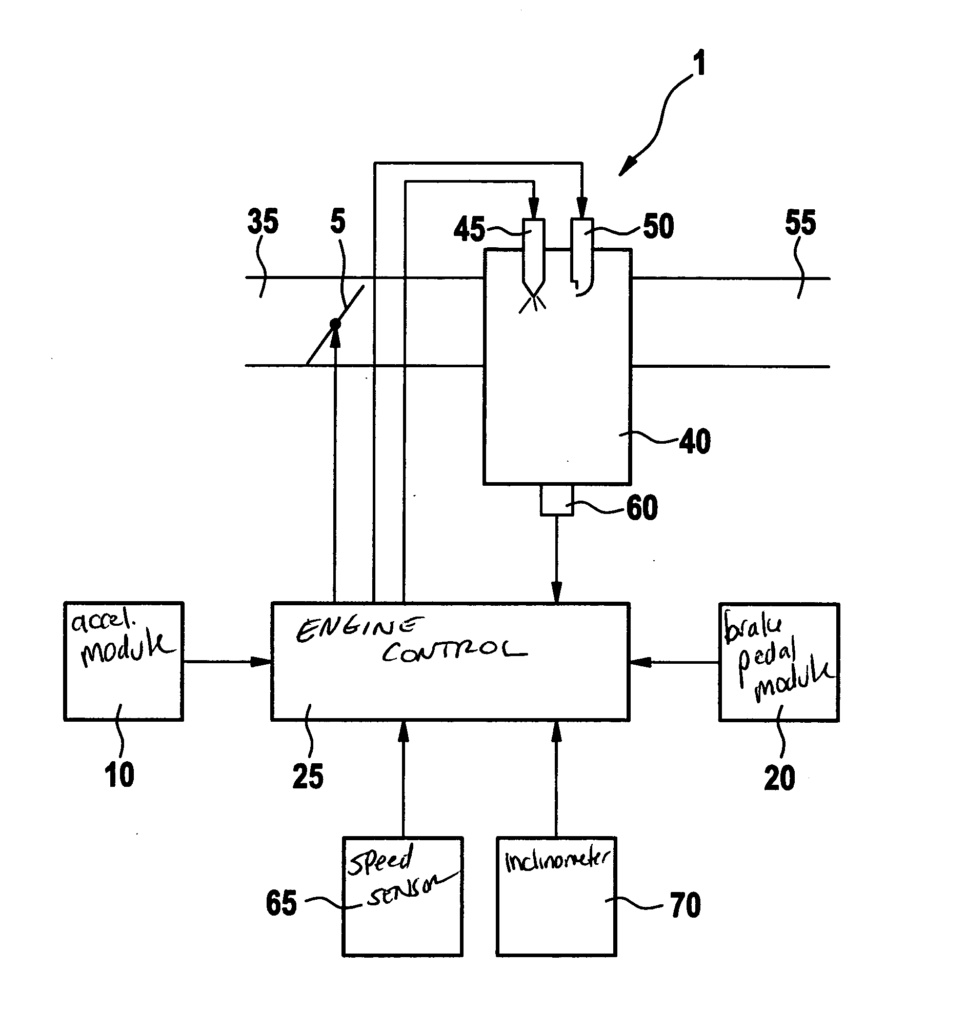
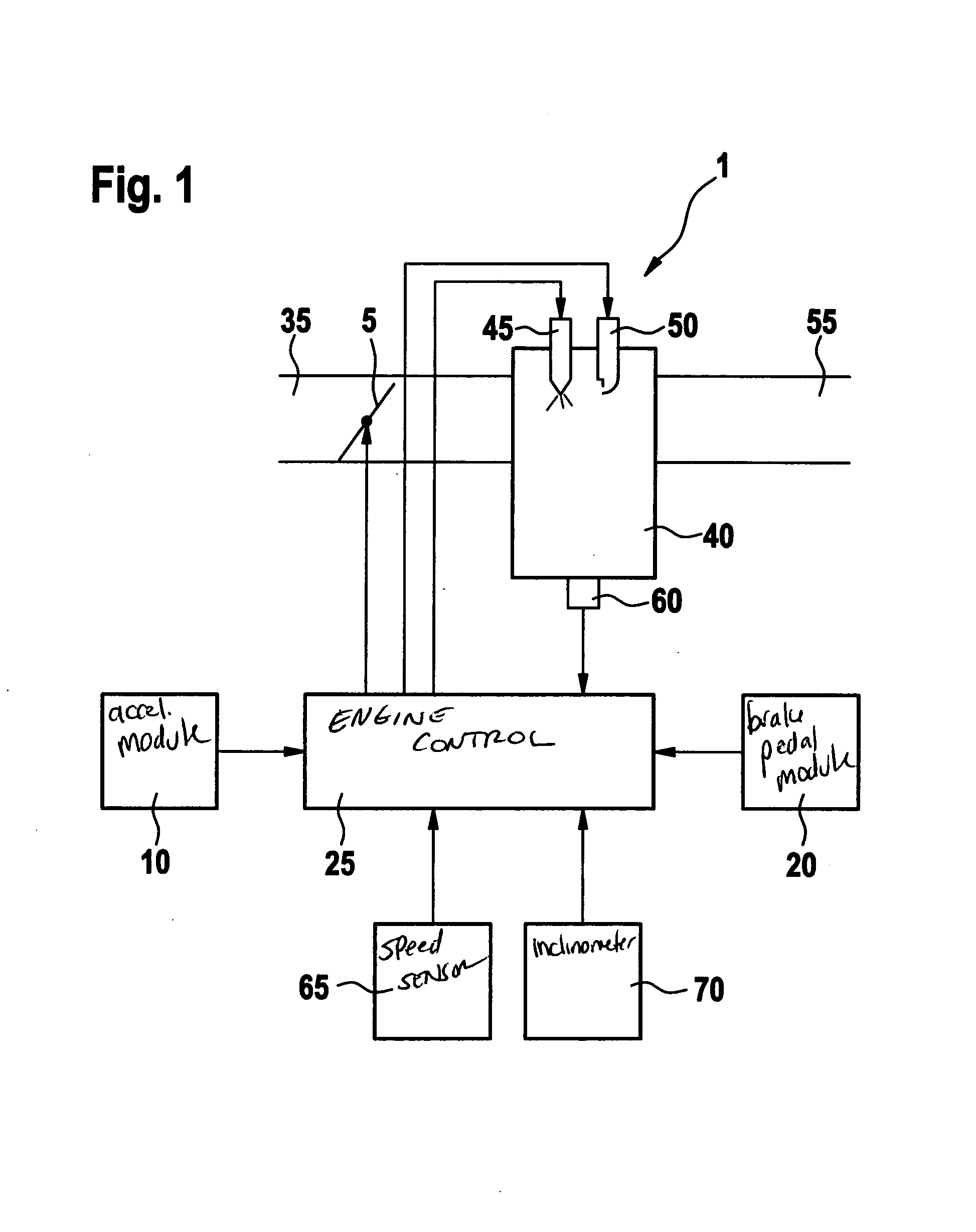
[0019] Reference numeral 1 in FIG. 1 denotes a combustion engine, which drives a vehicle and may be embodied as spark-ignition engine or diesel engine, for instance. In the following, it is assumed by way of example that internal combustion engine 1 takes the form of a spark-ignition engine. Combustion engine 1 includes one or more cylinder(s) 40 whose combustion chamber is supplied with combustion air via an air supply 35. Disposed in air supply 35 is an actuator 5, which is to be embodied as electronically controlled throttle valve in this example and whose opening degree is adjusted by an engine control 25. In this way, the cylinder charge is able to be set or controlled as a function of the opening degree of throttle valve 5. In the case of direct injection of fuel into individual cylinders 40, as indicated in FIG. 1, the fuel is injected directly into the combustion chamber of the corresponding cylinder via an individual fuel injector 45, the injection quantity and injection ti...


PUM


Abstract

A method and a device are provided for operating a vehicle having a combustion engine, which result in reduced fuel consumption in overrun operation. In the process, the air supply to the combustion engine is adjusted via an actuator. In overrun operation of the combustion engine, an opening degree of the actuator is set as a function of a driving situation.

Description

FIELD OF THE INVENTION [0001] The present invention relates to a method and a device for operating a vehicle having an internal combustion engine. BACKGROUND INFORMATION [0002] Methods and devices for operating a vehicle having an internal combustion engine in which the air supply to the combustion engine is adjusted via an actuator are conventional, a throttle valve generally being used as actuator. [0003] In modern spark-ignition engines, in overrun operation, the fuel injection is turned off whenever possible in an effort to lower the fuel consumption. The throttle valve is closed. This brings about a high brake torque of the combustion engine, the so-called engine brake. Due to the high engine-brake torque, the vehicle speed is considerably reduced in overrun operation. In certain driving situations this may not be intended, and the driver must leave overrun operation again after a short time. If the throttle valve were open in this case, a considerably lower engine-brake torque...

Claims


Application Information

Patent Timeline
IPC IPC(8): F02B75/12F02D9/02F02D11/10F02D29/02F02D35/00F02D37/02F02D41/00F02D41/02F02D41/04F02D41/10F02D41/12F02D41/22
CPCF02B2075/125F02D9/02F02D11/105F02D37/02F02D41/0005F02D41/021F02D2250/21F02D41/123F02D41/22F02D2200/501F02D2200/602F02D2200/702F02D2250/18F02D41/12
Inventor FRENZ, THOMASKUFFERATH, ANDREAS
Owner ROBERT BOSCH GMBH
Why Eureka
Try Eureka