Energy recovery ventilator

a technology energy recovery, which is applied in the field of airtoair heat exchangers, can solve the problems of difficult for a single person to efficiently and easily install prior art energy recovery ventilator units, cost and cumbersome installation, etc., and achieve the effect of saving installation time and cost, saving time and cost, and easy installation of energy recovery ventilators

Inactive Publication Date: 2005-06-23
RENEWAIRE
View PDF32 Cites 33 Cited by
  • Summary
  • Abstract
  • Description
  • Claims
  • Application Information

AI Technical Summary

Benefits of technology

[0017] There are a number of advantages of the present invention. First, the housing can mount directly to the return air duct of a heating or cooling system. Also, the housing requires only two separate duct pipes to be installed instead of four, saving installation time and cost. Installation of the energy recovery ventilator of the present invention is also very flexible because it can be installed in a number of different orientations and locations on the return air duct of a heating or cooling system, or on a wall, ceiling, or other mounting location as a stand-alone unit.
[0018] In addition, the hinged bar mountin

Problems solved by technology

The prior art energy recovery ventilator units are costly and cumbersome to install in that they require the installation of four separate duct pipes to carry each air stream to or from the fresh air or stale air spaces.
Further, it is difficult f

Method used


Image

  • Energy recovery ventilator
  • Energy recovery ventilator
  • Energy recovery ventilator

Examples


Embodiment Construction

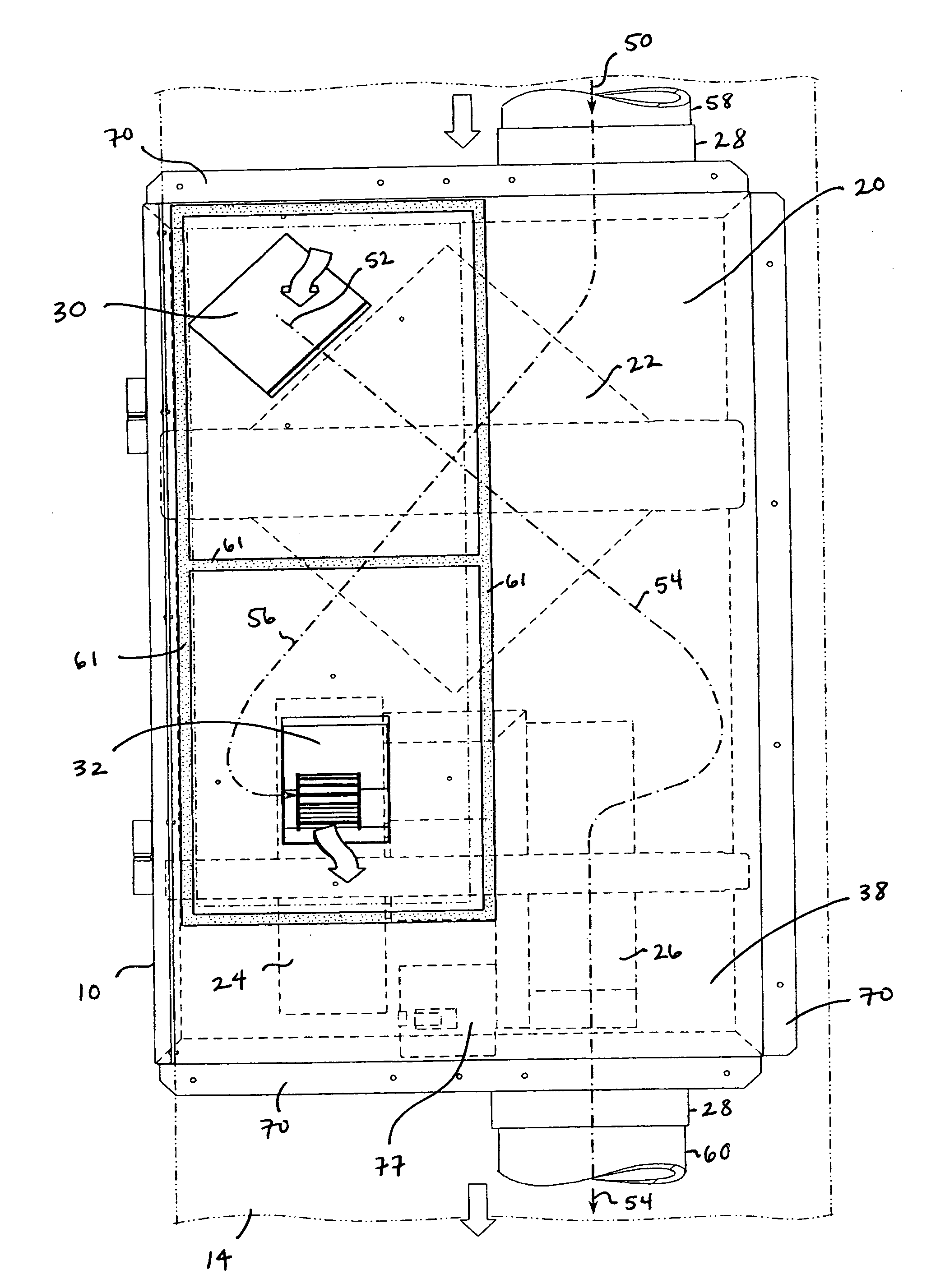
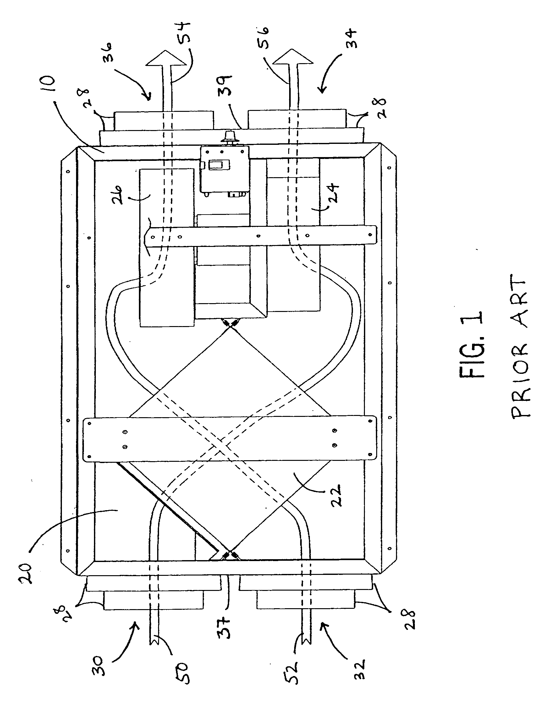
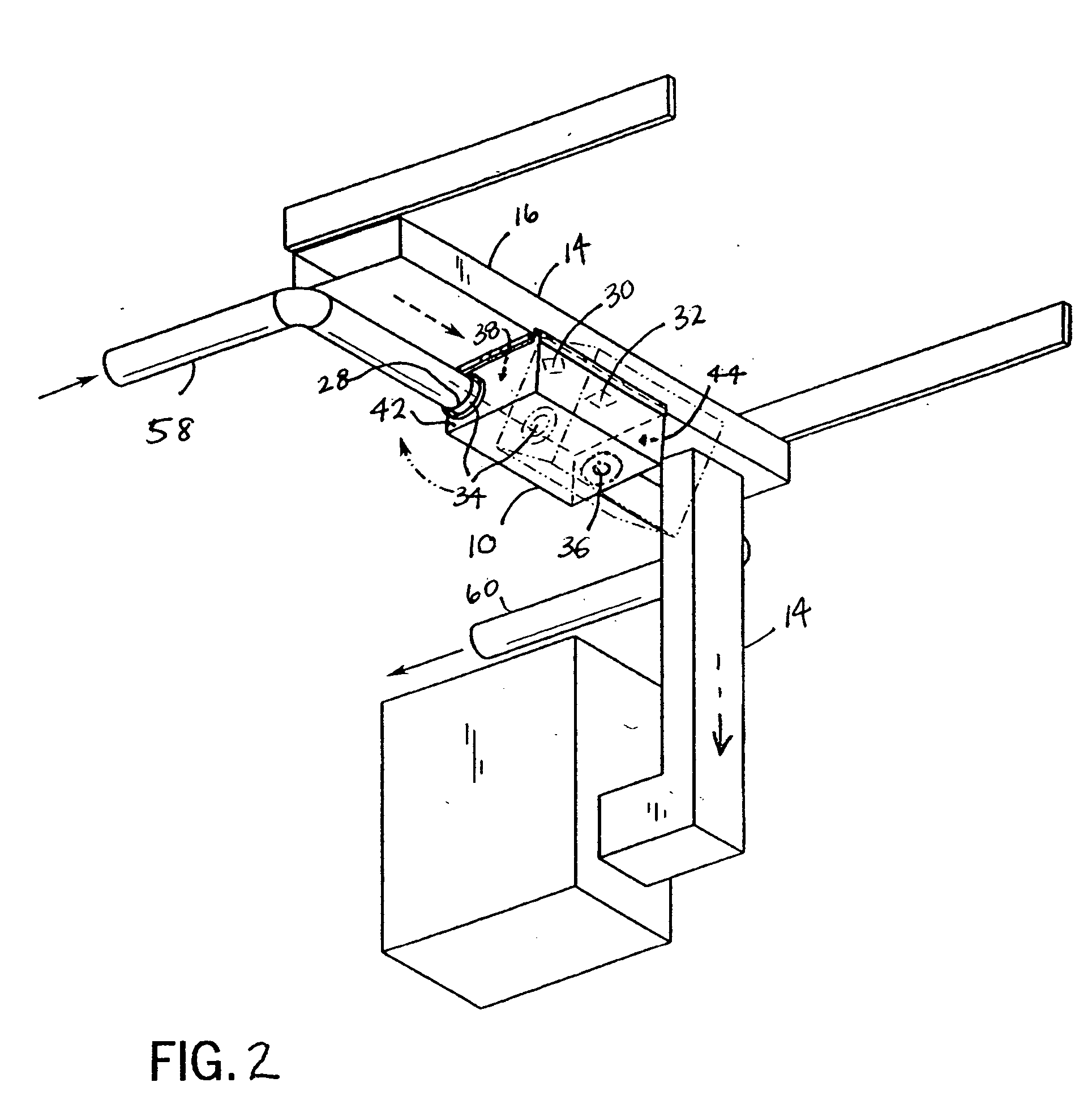
[0044] Referring again to the drawings, FIGS. 2, 3, 9 and 14 are isometric views of first, second, third and fourth embodiments of the present invention installed on a return air duct 14 of a heating or cooling system 12. In each of FIGS. 2, 3, 9, and 14, the energy recovery ventilator is shown as part of a ventilation system including a heating or cooling system 12, a heating or cooling mechanism 13, and a duct system including a return air duct 14. FIG. 2 shows a first embodiment, wherein the housing 10 is installed in a parallel orientation on the bottom of a horizontal section 16 of the return air duct 14. FIG. 3 shows a second embodiment, wherein the housing 10 is installed in a parallel orientation on the side of a vertical section 18 of a return air duct 14. FIG. 9 shows a third embodiment, wherein the housing 10 is installed in a perpendicular orientation on the bottom of a horizontal section 16 of a return air duct 14. FIG. 14 shows a fourth embodiment, wherein the housing ...


PUM


Abstract

An energy recovery ventilator wherein two of the air flow openings are in direct communication with either the fresh air space or the stale air space. The energy recovery ventilator has a housing with at least a first face panel holding a heat exchange device. The housing includes two air flow openings in the first face panel of the housing, in direct communication with the stale air space, and two other air flow openings in the housing in communication with the fresh air space through duct pipes. Alternatively, the first two air flow openings are in direct communication with the fresh air space, and the other two air flow openings are in communication with the stale air space through duct pipes. The energy recovery ventilator also includes a hinged bar mounting system and a control system. The features of the present invention facilitate ease of installation.

Description

BACKGROUND OF THE INVENTION [0001] The present invention relates generally to air-to-air heat exchangers, otherwise known as energy recovery ventilators, and more particularly to an energy recovery ventilator with features facilitating ease of installation. The design of the present invention provides a more efficient and more cost effective method for installing an energy recovery ventilator. [0002] An energy recovery ventilator is generally used to exhaust stale air from a stale air space to a fresh air space and bring in fresh air from the fresh air space to the stale air space while exchanging heat or cool energy, thereby reducing heating or cooling requirements associated with fresh air introduction. Energy recovery ventilators are often used in connection with a heating or cooling system, wherein the stale air space is sometimes a return air duct of the heating or cooling system, and the fresh air space is generally the outdoors. [0003] When in use with a heating or cooling sy...

Claims


Application Information

Patent Timeline
IPC IPC(8): F24F12/00F28F13/06
CPCY02B30/563F24F12/006Y02B30/56
Inventor GATES, CHARLESSTEEGE, DOUGLASFRIEDLANDER, MATTHEW L. C.
Owner RENEWAIRE
Why Eureka
Try Eureka