Multi-stage centrifugal debris trap

a centrifugal debris and multi-stage technology, applied in the direction of feed/discharge of settling tanks, vortex flow apparatus, machines/engines, etc., can solve the problems of damage to parts, damage to engine rotor groups, and damage to parts,

Inactive Publication Date: 2005-06-23
HONEYWELL INT INC
View PDF69 Cites 46 Cited by
  • Summary
  • Abstract
  • Description
  • Claims
  • Application Information

AI Technical Summary

Benefits of technology

[0010] In one aspect of the present invention, a centrifugal debris trap comprises a cylindrical chamber bound by an inner surface of a continuous wall radially disposed about a center axis at a first inner diameter; the inner surface separated from an outer surface of the continuous wall by a wall thickness; the continuous wall having a first wall end longitudinally separated along the center axis from a second wall end by a length; a plurality of grooves located between the first wall end and the second wall end; the plurality of grooves extending radially outward from the inner surface into a portion of the continuous wall; each of the plurality of grooves having a groove outer diameter that is greater than the first inner diameter; the cylindrical chamber being sealed at the first wall end by a back plate attached about a circumference of the first wall end; the cylindrical chamber being open at the second wall end through a ring attached to the second wall end about a circumference of the second wall end; the ring having a ring opening radially disposed about the center axis; and the ring opening having a second inner diameter less than the first inner diameter.

Problems solved by technology

Build related and other types of debris may be difficult to control and remove, in that they may remain within passages and conduits of various engine components in spite of attempts which may be made to remove such materials prior to engine startup.
Such debris may potentially damage parts which may be critical to engine operation prior to the debris being caught by the filtration system.
For example, debris located after a filtration system but prior to main shaft rotor bearings in, for example, a gas turbine, may result in a failed main shaft rotor bearing, which may result in destruction of an entire engine rotor group and / or destruction of various components such as a stator / shroud structure integral to an engine.
Bearing and other damage which may be caused by build-related debris may thus be considered a major source of premature bearing failure, and may also result in increased maintenance costs, warranty costs, and the like.
As with build-related debris, this debris may be difficult to control as it may be present after a filtration system but prior to, for example, a component requiring lubrication such as a bearing.
Such debris may also result in damage to a component and / or failure of an engine or system.
If such an arrangement is not present on a system, it may need to be incorporated into the design of the device, or may require the separator being located external to a component being protected, both of which may add complexity to a system.
While the magnetic member may retain a portion of the ferrous particles present, the magnetic member may not address removal of non-ferrous materials such as casting sand and other abrasive materials as described above.
Should such space not be available within a system or engine in which such a magnetic member is to be located, the magnetic member may require additional systems or space to be accommodated, which may add complexity to the system.

Method used


Image

  • Multi-stage centrifugal debris trap
  • Multi-stage centrifugal debris trap
  • Multi-stage centrifugal debris trap

Examples


Embodiment Construction

[0024] The following detailed description is of the best currently contemplated modes of carrying out the invention. The description is not to be taken in a limiting sense, but is made merely for the purpose of illustrating the general principles of the invention, since the scope of the invention is best defined by the appended claims.

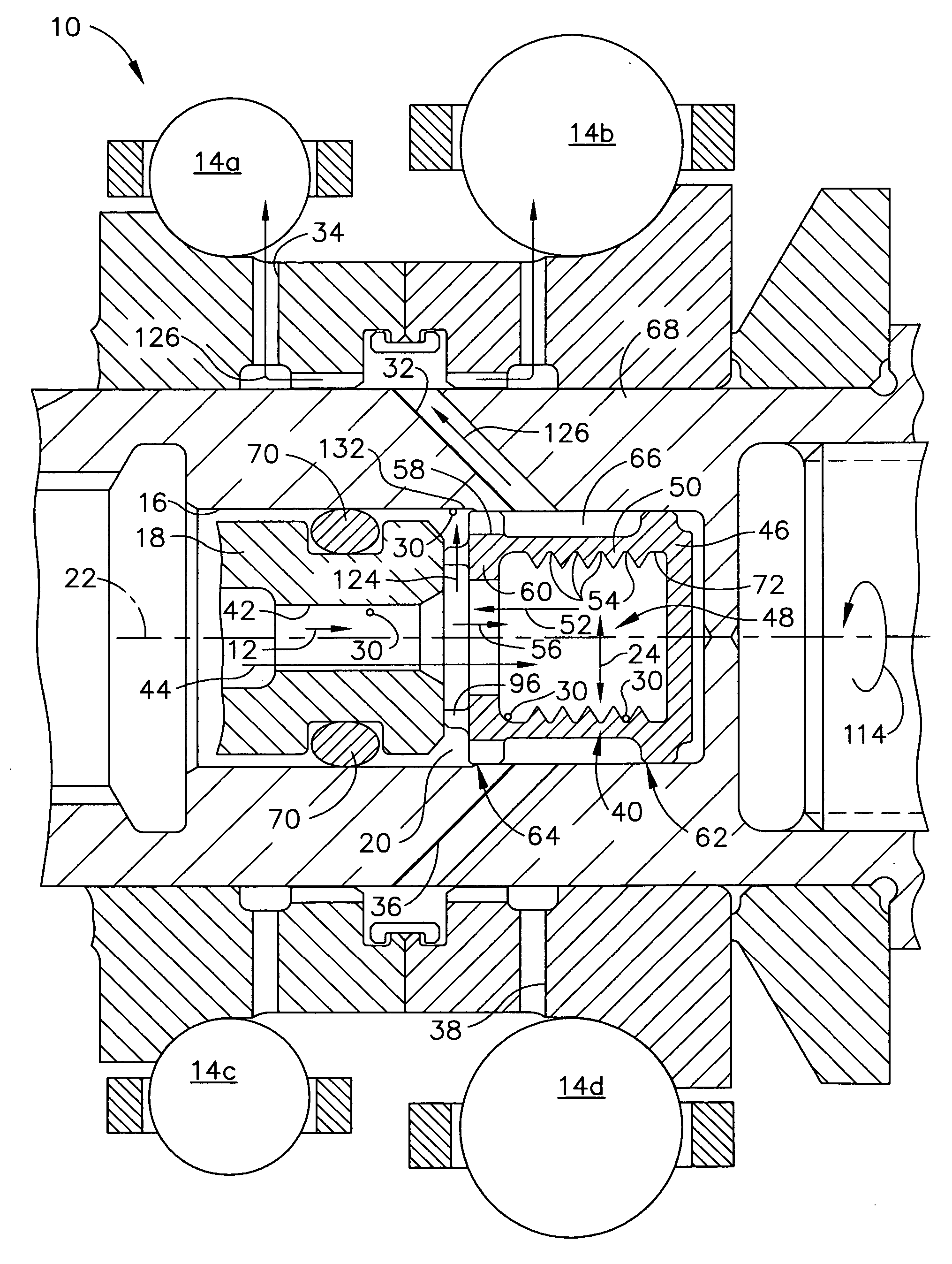
[0025] Broadly, the present invention generally provides for a multiple stage centrifugal separation device, generally referred to herein as a debris trap, and methods to remove debris from a fluid. In an embodiment, the present invention may be disposed integral to a system that may direct a fluid to some end use. In another embodiment, the fluid may be filtered and recycled back for use again. In yet another embodiment, the fluid in a system may be single use. This is counter to the prior art, in which debris traps may be provided in systems that recycle fluids.

[0026] In a further embodiment, the debris trap of the present invention may be integral...


PUM

PropertyMeasurementUnit
inner diameteraaaaaaaaaa

Abstract

A centrifugal debris trap has a plurality of stages which may trap debris which may be located in a fluid stream between or within components downstream of the filtration system. The centrifugal debris trap includes a cylindrical chamber bound by an inner surface of a continuous wall radially disposed about a center axis at a first inner diameter; the inner surface separated from an outer surface of the continuous wall by a wall thickness; the continuous wall having a first wall end longitudinally separated along the center axis from a second wall end by a length; a plurality of grooves located between the first wall end and the second wall end; the plurality of grooves extending radially outward from the inner surface into a portion of the continuous wall; each of the plurality of grooves having a groove outer diameter that is greater than the first inner diameter; the cylindrical chamber being sealed at the first wall end by a back plate attached about a circumference of the first wall end; the cylindrical chamber being open at the second wall end through a ring attached to the second wall end about a circumference of the second wall end; the ring having a ring opening radially disposed about the center axis; and the ring opening having a second inner diameter less than the first inner diameter.

Description

BACKGROUND OF THE INVENTION [0001] The present invention generally relates to apparatus and method for separating debris from a liquid stream, and more specifically, to a centrifugal debris trap useful to remove abrasive debris from a lubricating oil in an engine. [0002] During manufacture and / or repair of an engine or other components, various forms of debris, referred to as build-related debris, may be inadvertently incorporated therein. The types of debris may include abrasive materials such as metal shavings, dust, casting sand, and the like. Build related and other types of debris may be difficult to control and remove, in that they may remain within passages and conduits of various engine components in spite of attempts which may be made to remove such materials prior to engine startup. [0003] In an example, debris may be located downstream of a filtration system. Such debris may potentially damage parts which may be critical to engine operation prior to the debris being caugh...

Claims


Application Information

Patent Timeline
Patent Type & Authority Applications(United States)
IPC IPC(8): B01D21/26B04B1/02B04B5/00B04B7/08F01M11/03F16C19/56F16C33/66F16N39/06
CPCB04B1/02B04B5/005B04B7/08B04B2005/0457F01M11/03F01M2001/1035B01D21/262F16C33/667F16C33/6674F16C33/6677F16C33/6685F16N39/06F16C19/56F16C19/163F16C19/543F16C2360/23
Inventor BRIDGES, ERIC B.
Owner HONEYWELL INT INC
Why Eureka
Try Eureka