Tape cartridge

a cartridge and tape technology, applied in the field of tape cartridges, can solve the problems of rfid reader/writer not being able to identify the rfid tag, long access time of the cartridge, and inability to perform quite different performances, etc., and achieve the effect of shortening the time for searching

Inactive Publication Date: 2005-06-23
FUJIFILM HLDG CORP +1
View PDF13 Cites 31 Cited by
  • Summary
  • Abstract
  • Description
  • Claims
  • Application Information

AI Technical Summary

Benefits of technology

[0017] Herein, the term “management information” represents manufacture or usage historical information about the tape cartridge, information about a location of data on the magnetic tape, or the like, for example. By containing this management information on the RFID tag, the various operations of the magnetic tape can be made more efficient than a case where the magnetic tape contains the management information on its specific region. In other words, by containing this management information on the RFID tag, the need for writing the management information on the magnetic tape or for running the magnetic tape to read the management information therefrom is eliminated.
[0041] In conclusion, by providing the magnetic tape cartridge equipped with the RFID tag sensing means and the method for confirming condition of the RFID tag in the tape cartridge, which are both according to the present invention, it is possible to determine whether the RFID tag is set in the cartridge, with or without the RFID reader / writer, as well as to confirm, by working with the RFID reader / writer, the condition, etc. of the RFID tag having various specifications, thereby shortening the time for searching the RFID tag.

Problems solved by technology

Such magnetic tape cartridges, however, have a structure that a single magnetic tape contains data, and their access time inevitably ends up being long.
However, in an RFID tag as in the examples above, problems may occur, such as the positional relationship between an RFID tag and an RFID reader / writer is not optimum, or the performances of them are quite different from each other.
In these cases, the RFID reader / writer may fail to identify the RFID tag, or may spend a long time to search for the RFID tag.
These disadvantages may also appear when the specifications between the RFID tag and the RFID reader / writer are mismatched.
An RFID tag of this type may be damaged when being attached / detached to or from the magnetic tape cartridge.
In this case, the disadvantages above may also occur.

Method used


Image

  • Tape cartridge
  • Tape cartridge
  • Tape cartridge

Examples


first embodiment

(Arrangement)

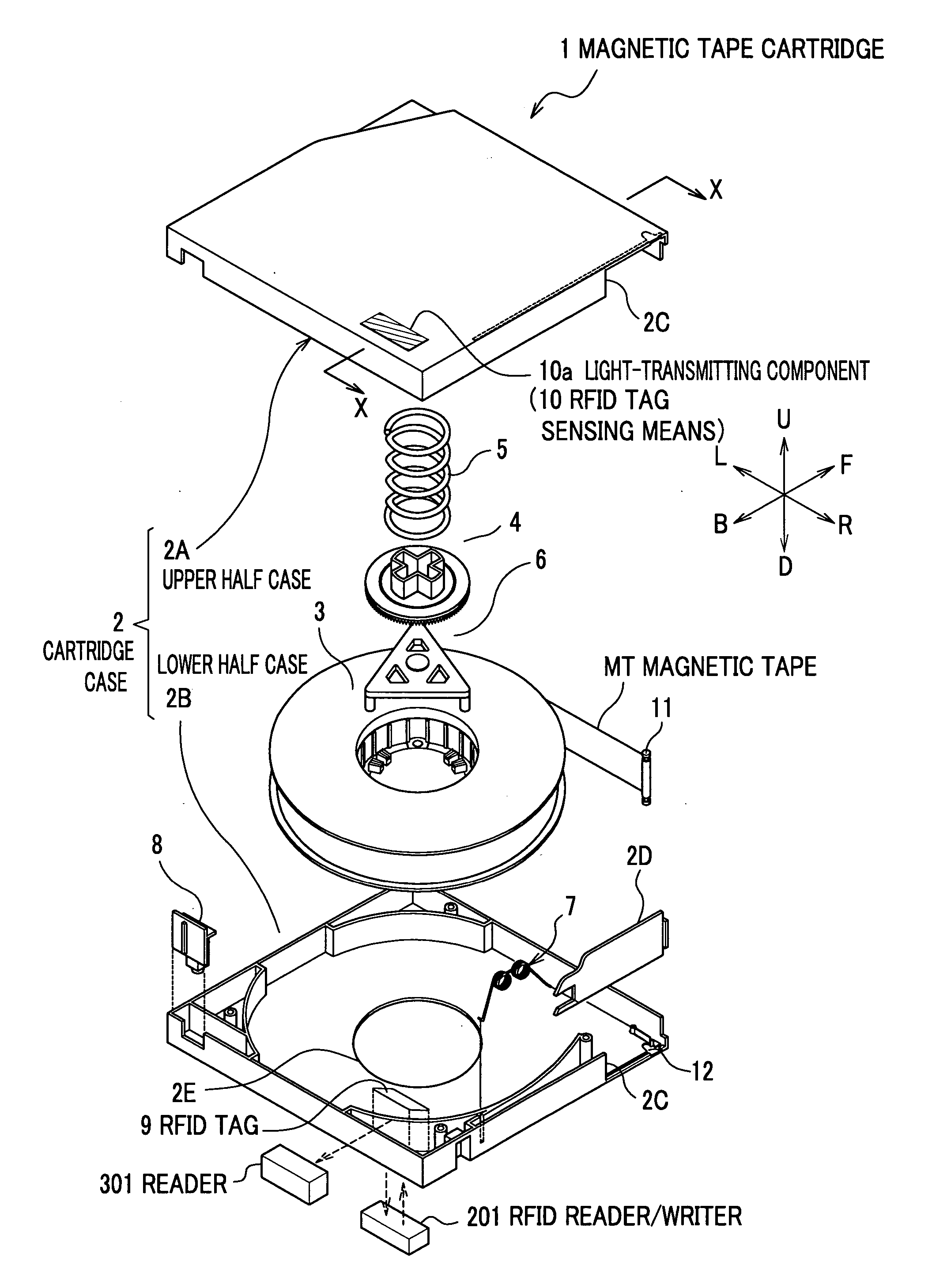
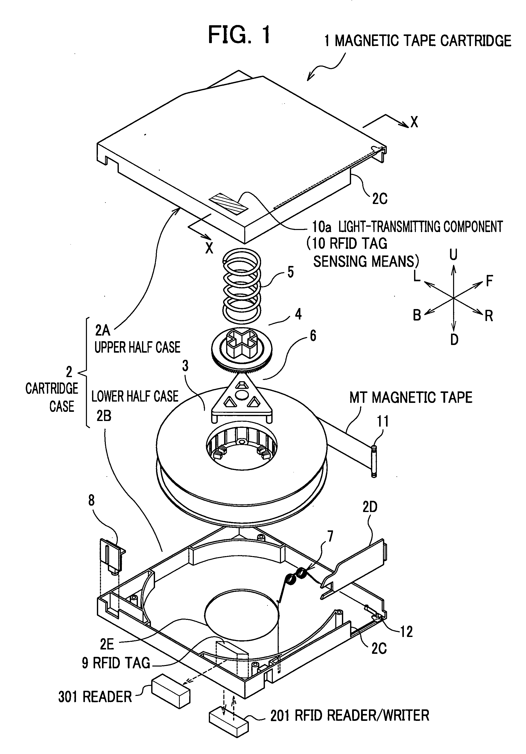
[0053] A description will be given below of a magnetic tape cartridge equipped with an RFID tag sensing means according to a first embodiment of the present invention, with reference to FIGS. 1 and 2. Referring to FIG. 1, the upper right direction (direction F) denotes a direction in which a magnetic tape cartridge 1 is loaded into a drive 200 (see FIG. 3). Referring to FIG. 2, the right direction (direction F) denotes the direction in which the magnetic tape cartridge 1 is loaded into the drive 200. The magnetic tape cartridge 1 shown in FIG. 1 is compliant with the LTO (Linear Tape-Open) standard, and includes, as main components: [0054] (a) a cartridge case 2 composed of upper and lower half cases 2A and 2B; [0055] (b) a magnetic tape MT; [0056] (c) a single reel 3 around which the magnetic tape MT is wound; [0057] (d) a reel lock 4 and a compressed coil spring 5 which both maintain the lock of the reel 3; [0058] (e) a release pad 6 which releases the lock of the r...

second embodiment

[0090] The magnetic tape cartridge 1 according to the second embodiment includes, as main components: [0091] (a) the RFID tag sensing means 10 constituted of light-transmitting components 10c and 10d arranged on the side and bottom of the lower half case 2B, respectively; and [0092] (b) the RFID tag 9 made of a material of a high reflectance ratio and inclined down 45 degrees in the direction F, as shown in FIG. 4A.

[0093] Specifically, the components of the RFID tag sensing means 10 are placed on the surfaces adjacent to each other, respectively. The light P passes through one of the surfaces, then reflects the RFID tag 9, and passes through the other surface.

[0094] The light P is emitted from the light emitting device 202A, then reaches the RFID tag 9 through the light-transmitting component 10c. Further, the light P is bent at a substantial right angle by reflecting the RFID tag 9. Subsequently, the light P passes through the light-transmitting component 10d, and is then receive...

third embodiment

[0099] The magnetic tape cartridge 1 according to the third embodiment includes, as main components: [0100] (a) the RFID tag sensing means 10 constituted of a light-transmitting component 10e provided on the rear edge of the cartridge case 2 (i.e. on the rear edge of the lower half case 2B in FIG. 4B) in the direction B; and [0101] (b) the RFID tag 9 is placed parallel to the light-transmitting component 10e, as shown in FIG. 4B.

[0102] Specifically, the RFID tag sensing means 10 is provided on one surface of the cartridge case 2, and the RFID tag 9 is placed parallel to the one surface.

[0103] The light P from the light emitting device 202A passes through the light-transmitting component 10e on the rear edge of the cartridge case 2, then reflects the RFID tag 9, and passes through the light-transmitting component 10e again. Finally, the light P is received by the light receiving device 202B. If the light P is received, then the result is that the RFID tag 9 is present and, otherwis...


PUM

PropertyMeasurementUnit
wavelengthaaaaaaaaaa

Abstract

Disclosed is a tape cartridge which contributes to shorten the time for sensing an RFID tag in the tape cartridge itself, and which makes it possible to sense the condition of the RFID tag. The tape cartridge includes a tape-shaped recording medium, an RFID tag for storing management information about the tape-shaped recording medium, a cartridge case containing the tape-shaped recording medium and the RFID tag, and an RFID tag sensing means making it possible to sense present of the RFID tag, the RFID tag sensing means being set in the cartridge case. In addition, the RFID tag sensing means includes two light-transmitting components for passing light therethrough, which are placed on a top surface of an upper half case of the cartridge case and on a bottom surface of a lower half case of the cartridge case, respectively, in alignment with the RFID tag.

Description

BACKGROUND OF THE INVENTION [0001] 1. Field of the Invention [0002] An apparatus consistent with the present invention relates to a tape cartridge and, especially to a magnetic tape cartridge containing a tape-shaped recording medium. More specifically, an apparatus consistent with the present invention relates to a magnetic tape cartridge which makes it possible to sense the presence of an RFID tag within. [0003] 2. Description of the Related Art [0004] Magnetic tape cartridges have been widely used as mass storage media. Such magnetic tape cartridges, however, have a structure that a single magnetic tape contains data, and their access time inevitably ends up being long. To overcome this disadvantage, a non-contact type of IC tag that functions as an automatic identifying means using radio waves or magnetic coupling has been produced, and a magnetic tape cartridge equipped with this IC tag has become popular. Hereinafter, an IC tag is referred to as “RFID (radio frequency identifi...

Claims


Application Information

Patent Timeline
Patent Type & Authority Applications(United States)
IPC IPC(8): G11B23/30G06F17/00G11B23/037
CPCG11B23/037
Inventor TADA, NOBUYUKI
Owner FUJIFILM HLDG CORP
Why Eureka
Try Eureka