Wing tip device
a technology of wing tip and wing blade, which is applied in the direction of influencers by generating vortices, aircraft control, aircraft components, etc., can solve the problems of dictating the weight of the wing, affecting the wing, and causing greater bending moments in the wing, so as to reduce the effect of divergent behaviour or flutter
- Summary
- Abstract
- Description
- Claims
- Application Information
AI Technical Summary
Benefits of technology
Problems solved by technology
Method used
Image
Examples
first embodiment
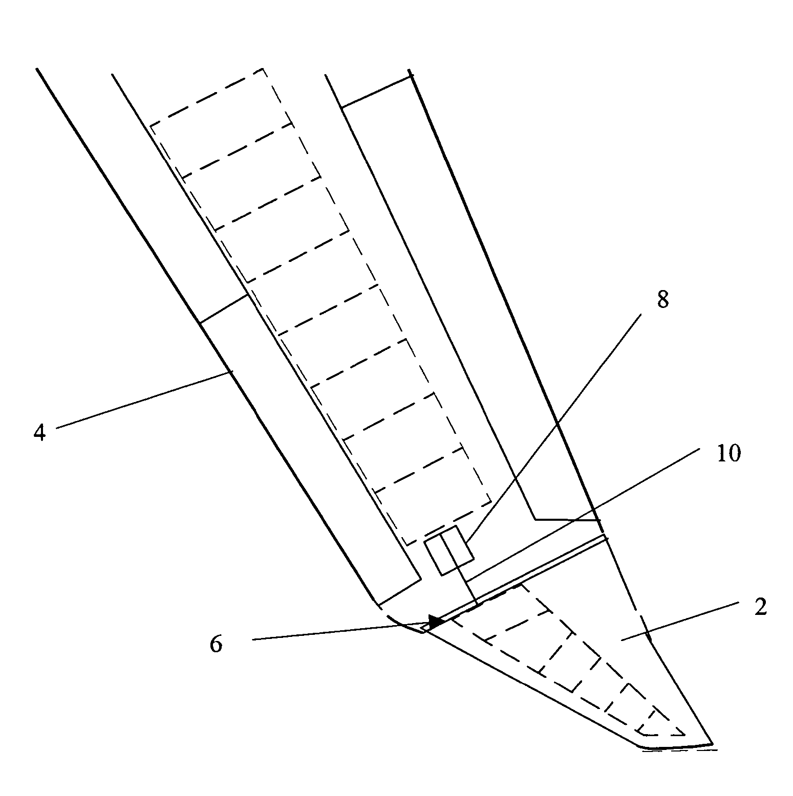
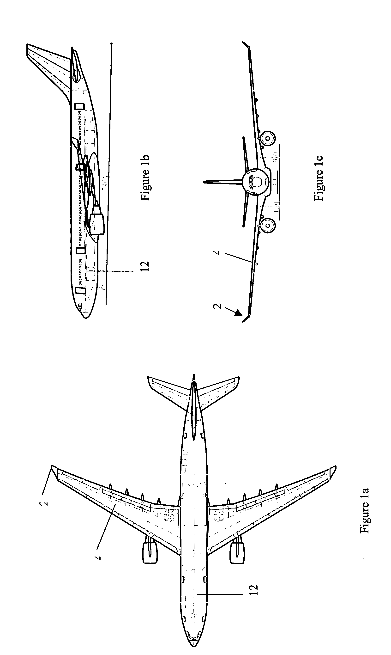
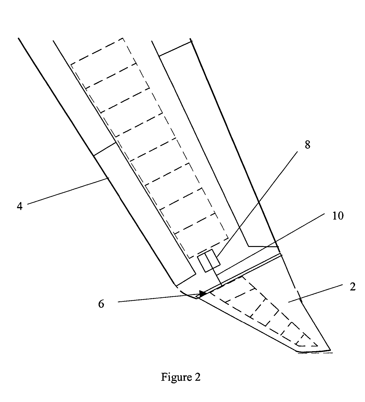
[0049] In this first embodiment of the invention, the position of the wing tip device 2 is actively controlled. When a high-load condition is detected or predicted, part of the flight controls computer sends signals that cause the rod 10 to move along the length of the wing 4 and away from the fuselage 12. The wing tip device 2 is constrained to pivot about the hinge 6 on the upper surface of the main wing 4. The action of the rod 10 therefore causes upward rotation of the wing tip device away from its first position 2a.
[0050] The airflow over the tip region of the wing 4 is disturbed, resulting in a loss of upward lift, a reduction in effective span and hence a reduction in bending moment at the root of the wing 4. Furthermore, the alignment of the hinge 6 is such that the mean incidence of the wing tip device 2 is reduced, decreasing the upward lift generated by the device and therefore further decreasing the bending moment at the root of the wing 4.
[0051] When the high-load con...
second embodiment
[0054] In this second embodiment, the wing tip device 102 is held in the first position during standard flight conditions and the wing tip device is controlled through active means. In the first position, the external surfaces of the wing tip device are flush with the adjacent external surfaces of the wing. When a high-load condition is detected or predicted, the actuator rotates the drive shaft 116 anticlockwise when viewed from the wing tip, rotating the wing tip device 102 leading edge down, to the second position. In the second position the edges of the wing tip device and wing that were parallel in the first position become non-parallel and the surfaces of the wing tip device and the wing are positioned so that they are no longer flush. The airflow over the tip region of the wing 104 is disturbed, resulting in a loss of upward lift, a reduction in effective span and hence a reduction in bending moment at the root of the wing 104. Furthermore, the mean incidence of the wing tip ...
fourth embodiment
[0061] It will be appreciated that various modifications may be made to the above-described embodiments of the invention. In each embodiment the wing tip device is in the form of a winglet, but the device could of course be in the form of any wing tip device that is able to improve aerodynamic efficiency when in the first position, but might cause high bending moments on the wing of the aircraft during high-load conditions. In such a modified embodiment, the device would be moveable to a second position in which the device reduces the bending moments in the main wing, for example in high-load conditions. The function of the flexible joint of the fourth embodiment may be provided by means of the wing, a portion thereof, the wing tip device, or a portion thereof, being made from an elastomeric material or a composite material having suitable resilient (springy) properties.
PUM
 Abstract
Description
Claims
Application Information
 - R&D
- Intellectual Property
- Life Sciences
- Materials
- Tech Scout
- Unparalleled Data Quality
- Higher Quality Content
- 60% Fewer Hallucinations
Browse by: Latest US Patents, China's latest patents, Technical Efficacy Thesaurus, Application Domain, Technology Topic, Popular Technical Reports.
© 2025 PatSnap. All rights reserved.Legal|Privacy policy|Modern Slavery Act Transparency Statement|Sitemap|About US| Contact US: help@patsnap.com


