Electromagnetic pulse transmitting system and method

a technology of electromagnetic pulse and transmitting system, which is applied in the direction of electric fuzes, nuclear reactors, greenhouse gas reduction, etc., can solve the problems of insufficient time for antenna deployment, large storage space for foldable antennas, and often required a large amount of tim

Inactive Publication Date: 2005-06-23
LOCKHEED MARTIN CORP
View PDF1 Cites 3 Cited by
  • Summary
  • Abstract
  • Description
  • Claims
  • Application Information

AI Technical Summary

Problems solved by technology

A substantial amount of time is often required to deploy such antennas, which results in additional planning to determine the appropriate time to begin deployment so that the antenna will be available when needed.
If the antenna has not been deployed, there may not be sufficient time to deploy the antenna and transmit the electromagnetic energy in the desired time frame.
Longer foldable antennas require more storage space, may be more complex, and generally take longer to unfold.

Method used


Image

  • Electromagnetic pulse transmitting system and method
  • Electromagnetic pulse transmitting system and method
  • Electromagnetic pulse transmitting system and method

Examples


first embodiment

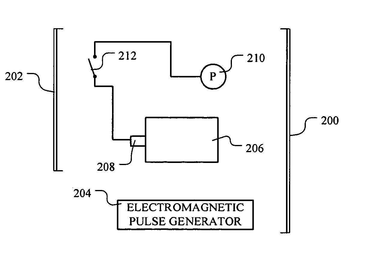
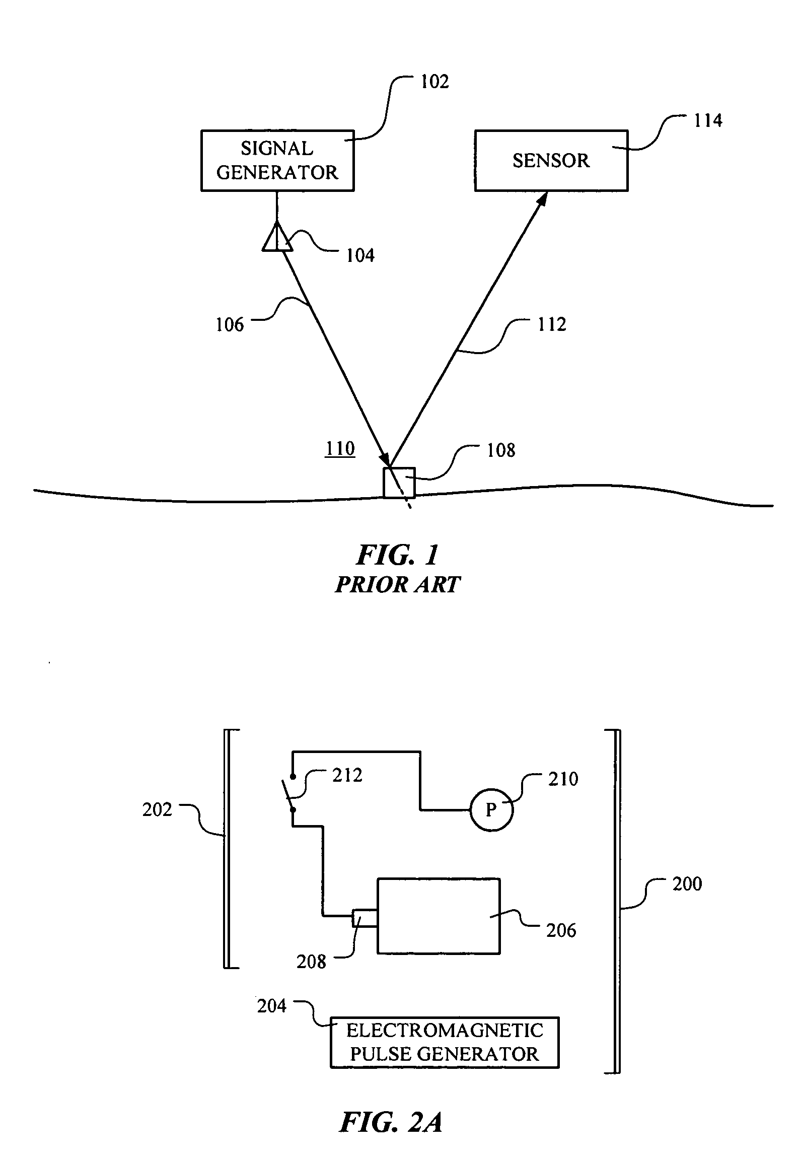
[0044] an electromagnetic pulse transmitting system according to the present invention is shown in FIGS. 2A and 2B. Referring to FIG. 2A, an electromagnetic pulse transmitting system 200 includes a plasma antenna generator 202 and an electromagnetic pulse generator 204. The plasma antenna generator 202 includes an explosive device 206 and a detonator 208 attached thereto for detonating the explosive device 206. A power source 210 is attached to the detonator 208 via a switch 212 that, when closed, provides a path for power from the power source 210 to fire the detonator 208 and detonate the explosive device 206. While a common throw-type switch is shown in FIG. 2 as the switch 212, the invention is not so limited. The switch 212 may be any switch known to the art.

[0045] The explosive device 206 includes an explosive charge (not shown), made of HMX (cyclotetramethylenetetranitramine), an HMX blend, RDX (cyclotrimethylenetrinitramine), an RDX blend, LX-14 (an HMX / estane blend), or the...

second embodiment

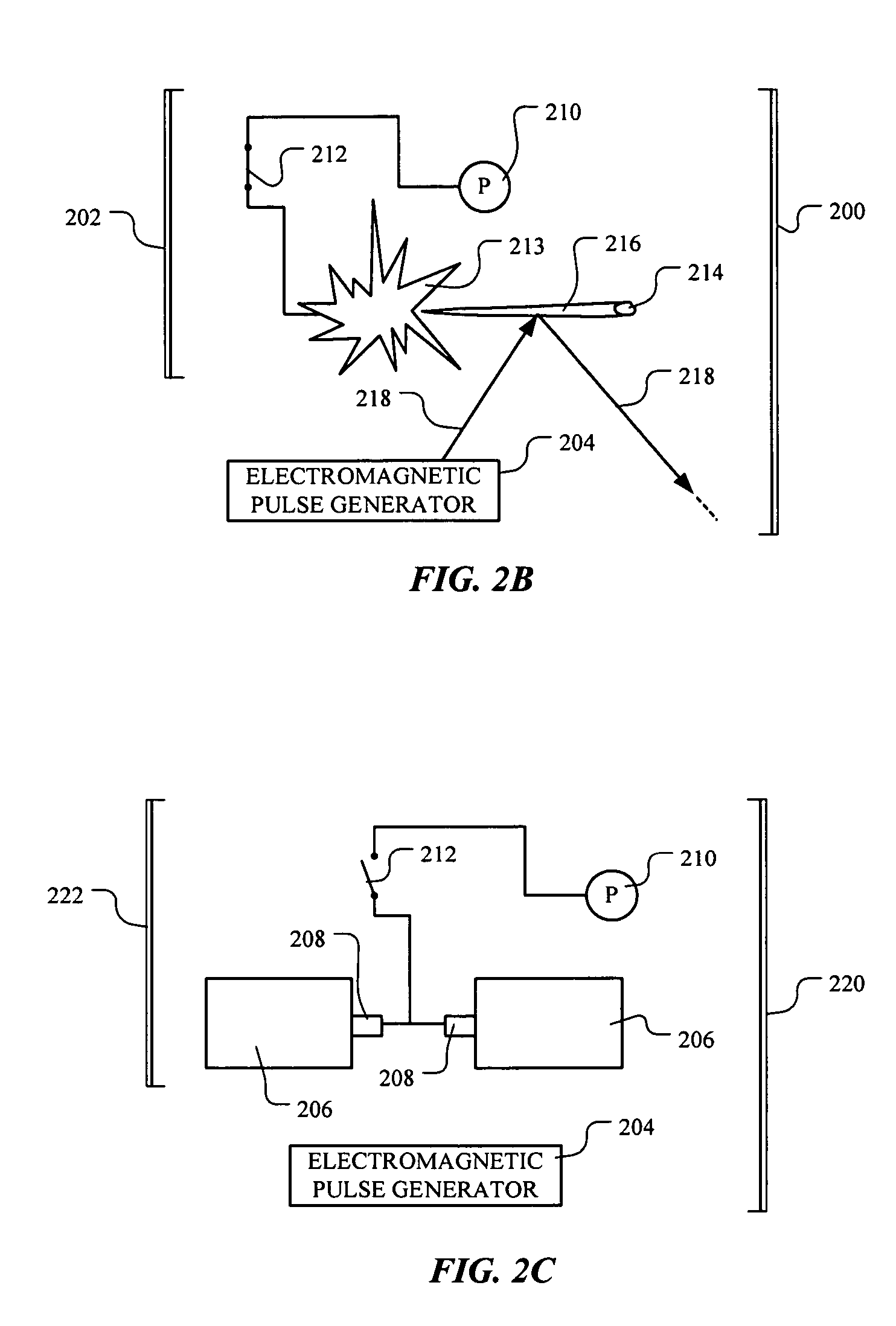
[0047] While the electromagnetic pulse transmitting system 200 illustrated in FIGS. 2A and 2B includes only one explosive device 206, the present invention is not so limited and may include any number of explosive devices 206. For example, in a second embodiment, an electromagnetic pulse transmitting system 220, as shown in FIG. 2C, comprises a plasma antenna generator 222 that includes two explosive devices 206. Upon detonating the explosive devices 206, particles 214 are propelled in different directions, as shown in FIG. 2D. The resulting plasma trails 216 form a dipole-like antenna for reradiating the electromagnetic pulse emitted from the electromagnetic pulse generator 204. Any of the explosive devices 206, if more than one is present, may be configured to propel the particles in any chosen, random, or chance direction with respect to any of the other explosive devices 206.

[0048] The ionizable material (not shown in FIGS. 2A and 2B) may be made from any material capable of bei...

fourth embodiment

[0065]FIGS. 8A and 8B illustrate the explosive device 206, 402 according to the present invention comprising a radial explosively formed projectile device 802. The device 802 comprises an explosive charge 804 partially encased by a casing 806. The explosive charge 804 may be made of any explosive material known in the art having a high detonation velocity and / or high brisance, as discussed above. The casing 806 defines a plurality of openings 808 in which are disposed a corresponding plurality of liners 810. The liners 810 comprise the ionizable material, as defined above, and any material known to the art as being suitable for explosively formed projectile device liners. For example, the liners 810 may be made of the ionizable material and copper or a copper alloy. Further, the liners 810 may have a construction such as that shown in FIGS. 5B or 5C. While the liners 810 shown in FIG. 8B are concavely shaped, the invention encompasses liners 810 having any chosen shape.

[0066] When t...


PUM

PropertyMeasurementUnit
detonation velocityaaaaaaaaaa
compressing energyaaaaaaaaaa
electromagneticaaaaaaaaaa

Abstract

A plasma antenna generator includes an ionizable material, an explosive charge capable of projecting the ionizable material upon detonation, and a detonator coupled with the explosive charge. An electromagnetic pulse transmitting system includes an electromagnetic pulse generator and a plasma antenna generator capable of reradiating an electromagnetic pulse emitted from the electromagnetic pulse generator. A method includes providing an explosive device comprising an ionizable material, detonating the explosive device to propel the ionizable material, and ionizing the ionizable material to form at least one plasma trail. A sensing system includes an electromagnetic pulse generator, a plasma antenna generator capable of reradiating an electromagnetic pulse emitted from the electromagnetic pulse generator, and a sensing system capable of receiving and analyzing at least a portion of the electromagnetic pulse after being reflected from an interface.

Description

BACKGROUND OF THE INVENTION [0001] 1. Field of the Invention [0002] This invention relates to a method and apparatus for transmitting an electromagnetic pulse. In one aspect, the invention relates to an electromagnetic pulse generator and a plasma antenna generator capable of forming a plasma antenna for reradiating an electromagnetic pulse from the electromagnetic pulse generator. [0003] 2. Description of the Related Art [0004] Electromagnetic energy can be used in many ways to sense or affect objects from a distance. Radar, for example, is reflected electromagnetic energy used to determine the velocity and location of a targeted object. It is widely used in such applications as aircraft and ship navigation, military reconnaissance, automobile speed checks, and weather observations. Electromagnetic energy may also be used to jam or otherwise interfere with radio frequency transmissions or to affect the radio transmitting equipment itself. [0005] In certain situations, it may be des...

Claims


Application Information

Patent Timeline
Patent Type & Authority Applications(United States)
IPC IPC(8): C06C5/00H01J7/24H05H1/24
CPCH05H1/52Y02E30/10
Inventor WOOD, JAMES R.MELIN, ROGER W.BROWDER, MARK K.CALICO, STEVE E.
Owner LOCKHEED MARTIN CORP
Why Eureka
Try Eureka