Stepping motor drive device and method

a technology of stepping motor and drive device, which is applied in the direction of electric controllers, dynamo-electric converter control, instruments, etc., can solve the problems of slow attenuation of coil current at the time of the staircase signal decreasing, poor follow-up of coil current of the staircase signal, and degradation of the recorded image, etc., to achieve rapid rate, reduce vibration and noise, and enhance power supply efficiency

Active Publication Date: 2005-06-23
COLLABO INNOVATIONS INC
View PDF9 Cites 10 Cited by
  • Summary
  • Abstract
  • Description
  • Claims
  • Application Information

AI Technical Summary

Benefits of technology

[0023] In the view toward achieving a reduction in vibration and noise, suppose that, for example, an approximate sinusoidal staircase signal is used as the reference signal for controlling the coil current. In this case, by prohibiting the synchronous rectification, a stepping motor drive device with the above configurations makes the coil current decay rapidly during a period when the reference signal is decreasing at a relatively rapid rate. Herewith, the coil current follows the limit indicator precisely. In the time other than the above period, on the other hand, the power supply efficiency is enhanced by carrying out the synchronous rectification and thereby mitigating decay of the coil current.
[0024] Thus, providing implementation and prohibition periods of the synchronous rectification according to the decreasing rate of the reference signal allows to achieve a reduction in vibration and noise as well as a good efficiency in the power supply.
[0025] In addition, the stepping motor drive device of the present invention exercises a PWM control on the supply current to the coil, using a current chopper method. This achieves lower power operation compared to the case where the current is supplied to the coil by voltage control.
[0026] Here, the synchronous rectification prohibition unit may (i) acquire a specification signal which specifies one of a plurality of different portions of a time period during which the limit indicator is decreasing, and (ii) during the specified portion, prohibit the synchronous rectification control unit from bringing the synchronous rectification unit into the conducting state.
[0027] With this configuration, the prohibition time portion of the synchronous rectification set during the time when the limit indicator is decreasing can be varied according to the specification signal.
[0028] When the reference signal is for instance an approximate sinusoidal staircase signal, it is generally preferred that, as the frequency of the staircase signal becomes higher, the synchronous rectification is prohibited for a longer portion of time when the limit indicator is decreasing. Here, appropriate control in response to changes in the frequency of the frequency of the staircase signal can be achieved by providing the specification signal based on the frequency. Furthermore, when the amplitude of the reference signal is to be adjusted in order to control the torque, it is also possible to achieve appropriate control in response to changes in the amplitude.

Problems solved by technology

This is because sounds generated by a stepping motor are caught by a built-in microphone of the electronics device and recorded as noise, while vibrations generated by a stepping motor cause image blurring and result in degradation of the recorded image.
However, as to the drive device of the related art above, the attenuation of the coil current at the time when the staircase signal is decreasing is slow, and therefore the coil current poorly follows the staircase signal.
As a result, this presents the first problem that an intended reduction in vibration and noise cannot be obtained.
This is a serious problem particularly when the stepping motor is applied to image capturing electronics devices, and thus there is still a demand for further reduction in noise and vibration of the stepping motor operations.
In addition, there is a second problem that the drive device of the above related art requires a considerable amount of power since the coil current is continuously supplied.

Method used


Image

  • Stepping motor drive device and method
  • Stepping motor drive device and method
  • Stepping motor drive device and method

Examples


first embodiment

1. First Embodiment

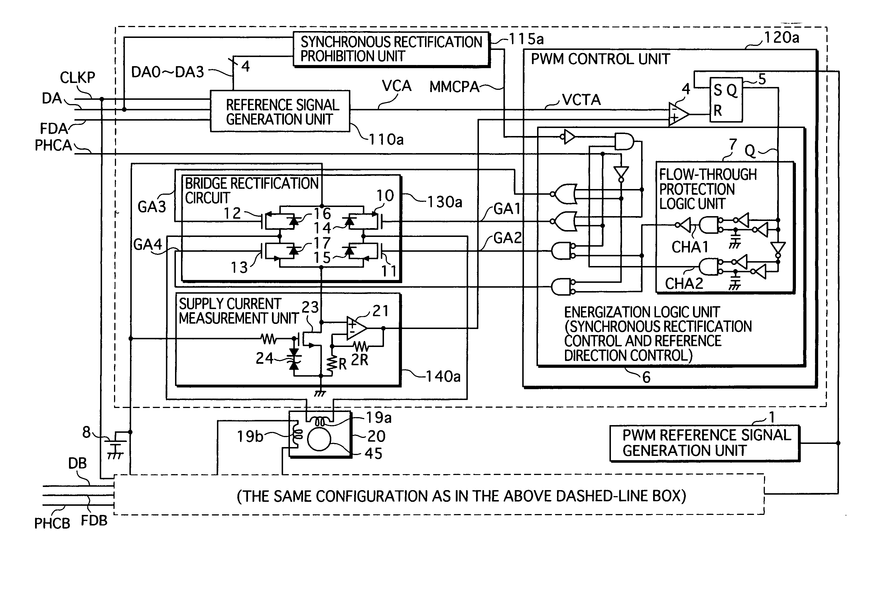
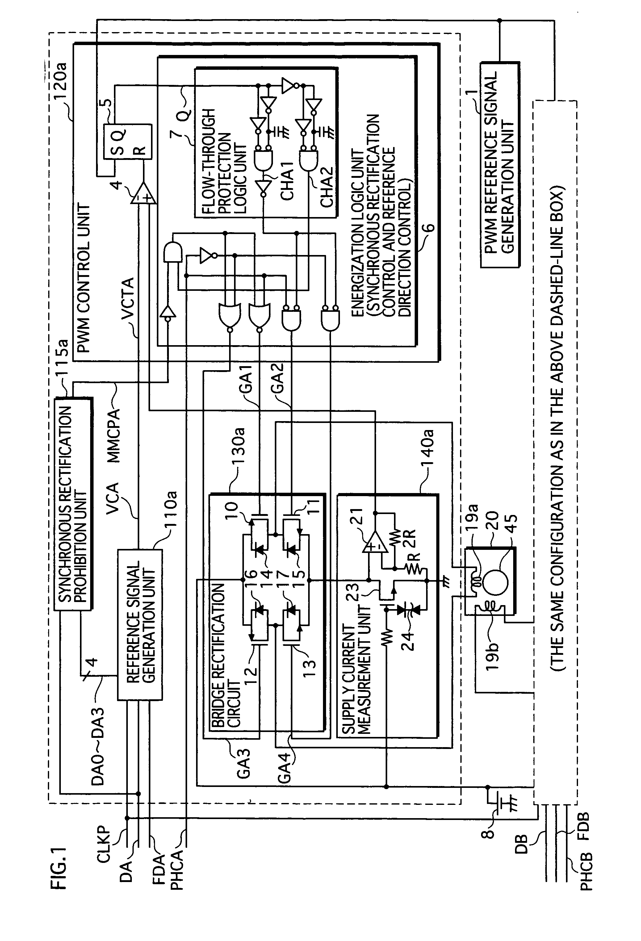
[0075] A stepping motor drive device of the first embodiment of the present invention generates a reference signal that represents a limit indicator, and exercises PWM (Pulse Width Modulation) control on a current supplied to the motor coil, according to the limit indicator. More specifically, the PWM control is executed using a current chopper method.

[0076] In addition, the stepping motor drive device implements synchronous rectification. In this rectification process, a switch for the synchronous rectification is brought into conduction and forms a closed circuit together with the motor coil during the period when the current supply to the motor coil is stopped. In this closed circuit, a regenerative current from the motor coil is circulated through the switch. However, the switch drops out of conduction at least for a period of time when the limit indicator represented by the reference signal is decreasing, and the regenerative current from the motor coil is c...

second embodiment

2. Second Embodiment

[0127] A stepping motor drive device of the second embodiment of the present invention differs from the first embodiment in the configuration relevant to the SR prohibition signal MMCPA generation. The following mainly describes the differences of the second embodiment from the first embodiment.

2.1 Overall Configuration

[0128]FIG. 11 is a functional block diagram showing an overall configuration of the stepping motor drive device of the second embodiment. Compared to the first embodiment, a SR prohibition unit 117a is used, instead of the SR prohibition unit 115a.

[0129] The SR prohibition unit 117a is configured so as to vary the time portion of which the SR prohibition signal MMCPA is being outputted according to program signals PRGA0 and PRGA1 provided from outside.

2.2 SR Prohibition Unit 117a

[0130]FIG. 12 is a functional block diagram showing a detailed configuration of the SR prohibition unit 117a. When the count value DA0-DA3 is between 0 and 7, the SR p...

third embodiment

3. Third Embodiment

[0133] A stepping motor drive device of the third embodiment of the present invention differs from the first embodiment in that a unit for delaying the polarity signal is added. The following mainly describes the differences of the third embodiment from the first embodiment.

3.1 Overall Configuration

[0134]FIG. 13 is a functional block diagram showing an overall configuration of a stepping motor drive device according to the third embodiment. Note that a stepping motor which is driven by the device, is also shown in the figure. This stepping motor drive device is configured by adding a timing adjustment unit 116a to the first embodiment (see FIG. 1). The timing adjustment unit 116a outputs the polarity signal PHCA, to the energization logic unit 6, with a delay of a specified period of time.

3.2 Timing Adjustment Unit 116a

[0135]FIG. 14 is a functional block diagram showing a detailed configuration of the timing adjustment unit 116a. Being input the polarity signa...


PUM


Abstract

A reference signal generation unit 110a generates a reference signal VCA representing a limit indicator. Under the control of a PWM control unit 120a, a bridge rectification circuit 130a controls the current supplied to a coil 19a to the limit indicator, using a current chopper method. Therewith, the circuit 130a implements synchronous rectification where transistors 10 and 12 are brought into conduction when the current supply is stopped, forming a closed circuit with the coil 19a, and a regenerative current circulates in the closed circuit. During a time period when the reference signal is decreasing relatively rapidly, a SR prohibition unit 115a prohibits the transistor 10 or 12 from being brought into conduction when the current supply is stopped, and thereby the decay of regenerative current is accelerated.

Description

BACKGROUND OF THE INVENTION [0001] 1. Field of the Invention [0002] The present invention relates to a stepping motor drive device, in particular to a technology for driving a stepping motor with low noise and low vibration. [0003] 2. Description of the Related Art [0004] Late years, stepping motors are used in image capturing electronics devices, such as a DSC (Digital Still Camera) and a DVC (Digital Video Camera), as optical system actuators for adjusting aperture, focus, zoom and so on. [0005] Stepping motors, especially those used for image capturing electronics devices, are required to operate with low noise and low vibration. This is because sounds generated by a stepping motor are caught by a built-in microphone of the electronics device and recorded as noise, while vibrations generated by a stepping motor cause image blurring and result in degradation of the recorded image. [0006] In response to such a demand, a drive technology for stepping motor operations with low noise ...

Claims


Application Information

Patent Timeline
Patent Type & Authority Applications(United States)
IPC IPC(8): H02P8/10H02P8/32
CPCH02P8/32
Inventor FUKAMIZU, SHINGOONISHI, KATSUHIRO
Owner COLLABO INNOVATIONS INC
Why Eureka
Try Eureka