Doherty amplifier

Inactive Publication Date: 2005-06-23
TELEFON AB LM ERICSSON (PUBL)
View PDF1 Cites 62 Cited by
  • Summary
  • Abstract
  • Description
  • Claims
  • Application Information

AI Technical Summary

Problems solved by technology

However, because most highly efficient amplifiers operate in saturation, there is a trade-off between high efficiency and linearity.

Method used


Image

  • Doherty amplifier
  • Doherty amplifier
  • Doherty amplifier

Examples


Embodiment Construction

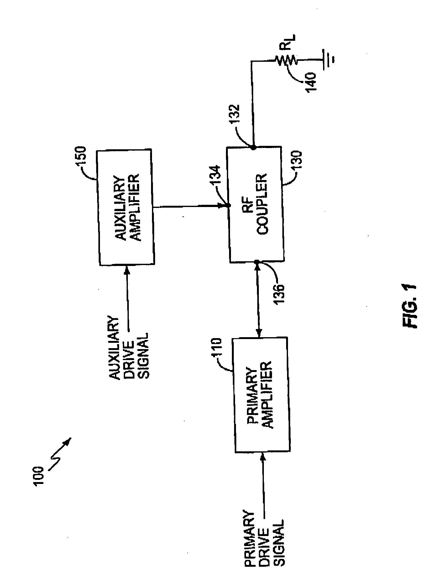
[0027] In each of the above described amplification systems, the auxiliary amplifier is directly connected to the output of the primary amplifier, even when the auxiliary amplifier does not contribute any power to the load. The auxiliary amplifier increases the total losses associated with the amplifier circuit. To minimize these losses, the auxiliary amplifier may be tuned to present a high output impedance at the junction between the primary and auxiliary amplifiers so that the auxiliary amplifier looks like an open circuit to the primary amplifier when the auxiliary amplifier is not contributing any power to the load. However, when used in systems operating at microwave frequencies, the high output impedance may be difficult to achieve.

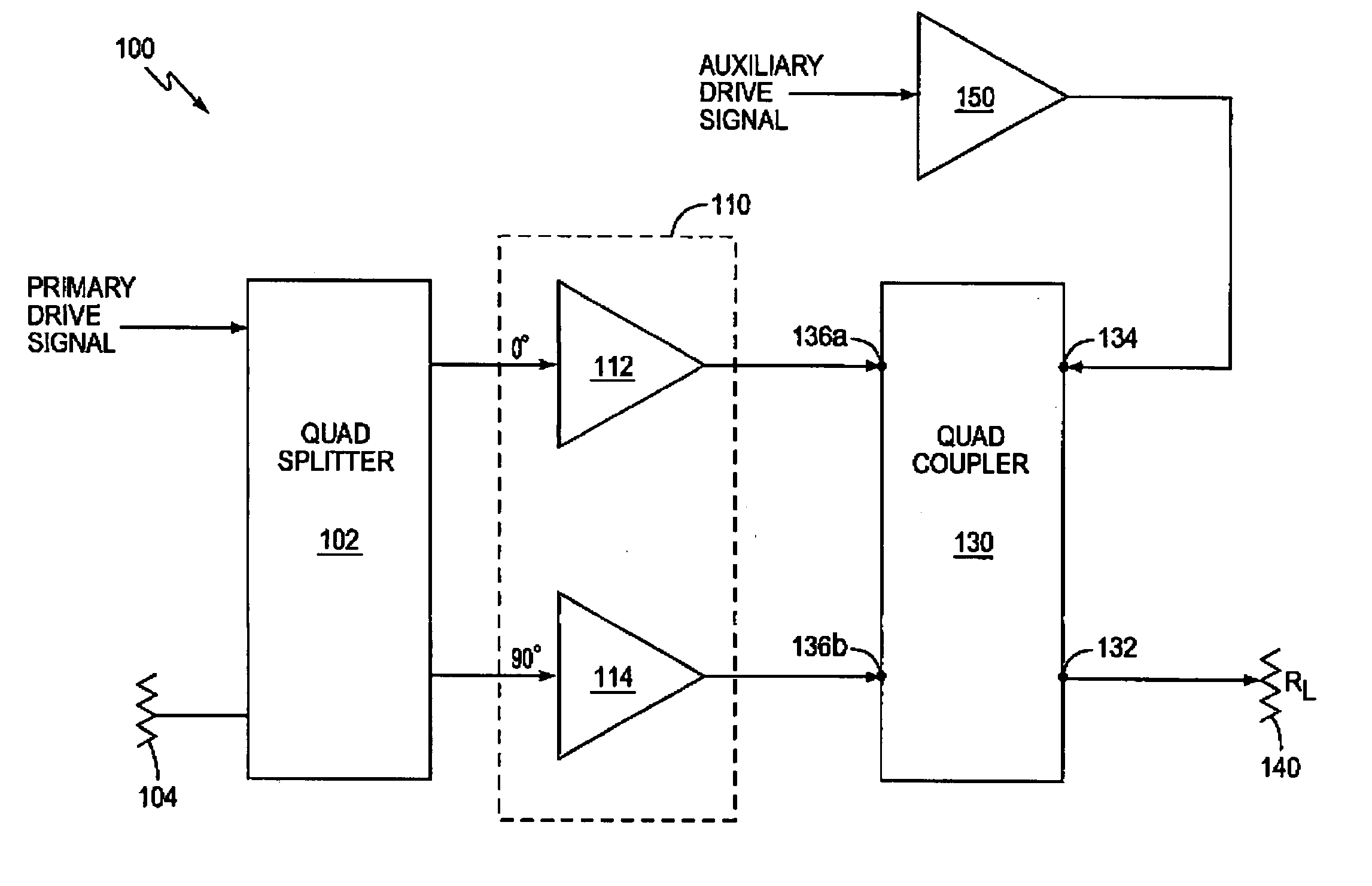
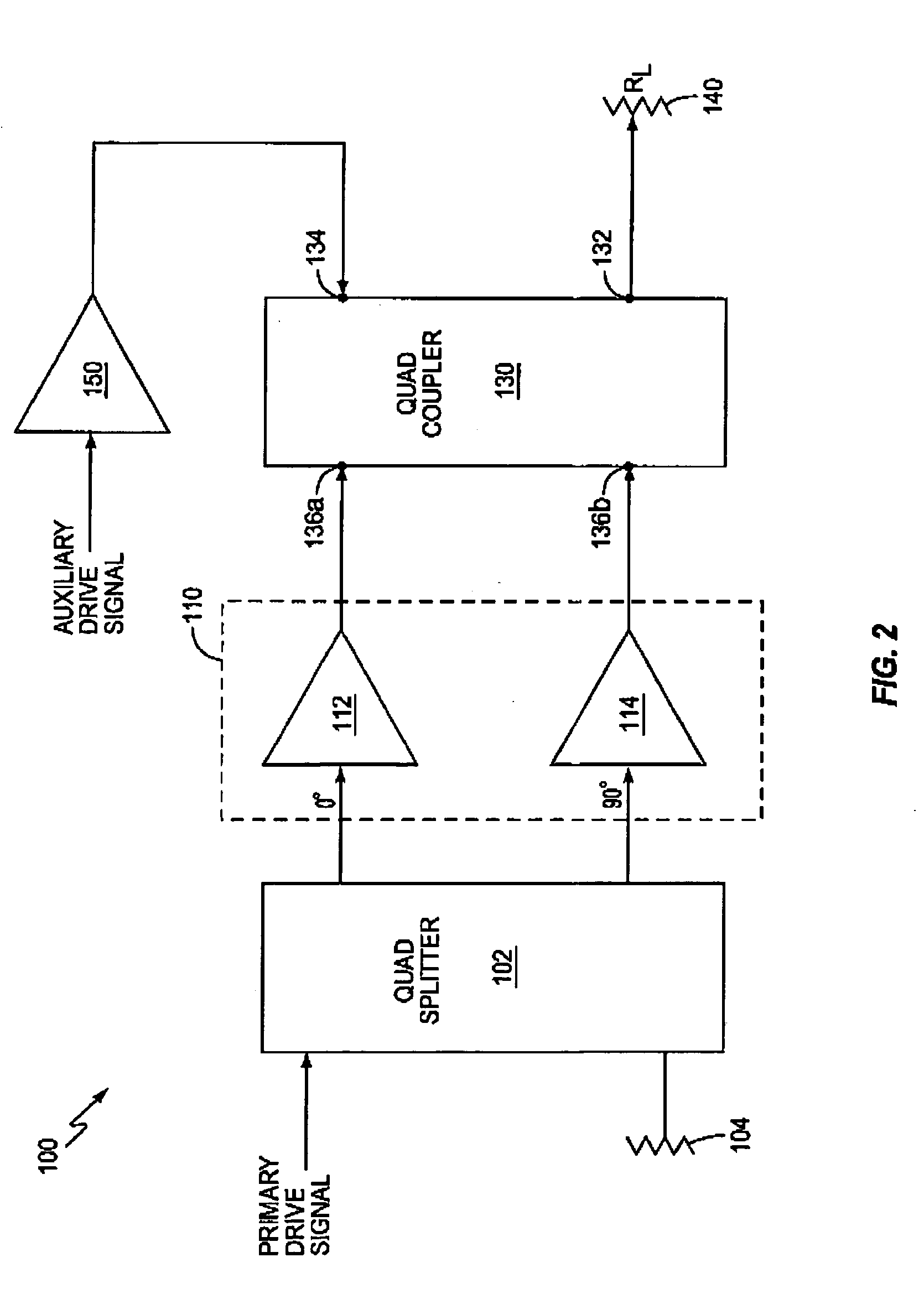
[0028]FIG. 1 illustrates a block diagram for an exemplary amplifier circuit 100 according to the present invention. Amplifier circuit 100 is applicable to any wireless transmitter, such as the base station and / or mobile terminal transmitter. The t...


PUM


Abstract

An efficient linear amplifier according to the present invention comprises a primary amplifier for providing power to a load and an auxiliary amplifier for generating an artificial reflection signal. The artificial reflection signal may have a predetermined phase difference as compared to the output signal supplied to the load. The amplifying circuit also includes a coupler connecting the primary amplifier to the load. The coupler includes a load port connected to the load, a primary port connected to an output of the primary amplifier, and an auxiliary port connected to an output of the auxiliary amplifier such that the artificial reflection signal changes an apparent impedance of the load as seen by the primary amplifier.

Description

BACKGROUND OF THE INVENTION [0001] The present invention relates generally to amplifiers and more particularly to an efficient linear amplifier circuit for amplifying radio frequency (RF) signals of varying amplitude. [0002] Linear power amplifiers are widely used in wireless communication systems to amplify signals transmitted between a base station and a mobile terminal. Because power is at a premium in wireless communication systems, particularly in the mobile terminals, it is desirable for the power amplifiers to provide highly efficient linear amplification. However, because most highly efficient amplifiers operate in saturation, there is a trade-off between high efficiency and linearity. [0003] U.S. Pat. No. 2,210,028 to Doherty describes a vacuum tube amplification system that provides efficient linear amplification for input signals. The Doherty amplifier comprises two vacuum tube amplifiers connected in parallel at their outputs with a quarter wavelength transmission line. ...

Claims


Application Information

Patent Timeline
Patent Type & Authority Applications(United States)
IPC IPC(8): H03F1/02
CPCH03F1/0288
Inventor DENT, PAUL W.
Owner TELEFON AB LM ERICSSON (PUBL)
Why Eureka
Try Eureka