Vehicle display system

a technology of vehicle display and display screen, which is applied in the field of vehicle display screen, can solve the problem that the driver cannot sufficiently observe the peripheral road sign

Inactive Publication Date: 2005-06-23
DENSO CORP
View PDF23 Cites 72 Cited by
  • Summary
  • Abstract
  • Description
  • Claims
  • Application Information

AI Technical Summary

Benefits of technology

[0010] In this structure, a color image of a forward scenery and also a generated display image are displayed by being superimposed with each other on a head-up display or a display

Problems solved by technology

When a driver pays attention to a pedestrian or another vehicle during the driving

Method used


Image

  • Vehicle display system
  • Vehicle display system
  • Vehicle display system

Examples


modification 1

[0050] (Modification 1)

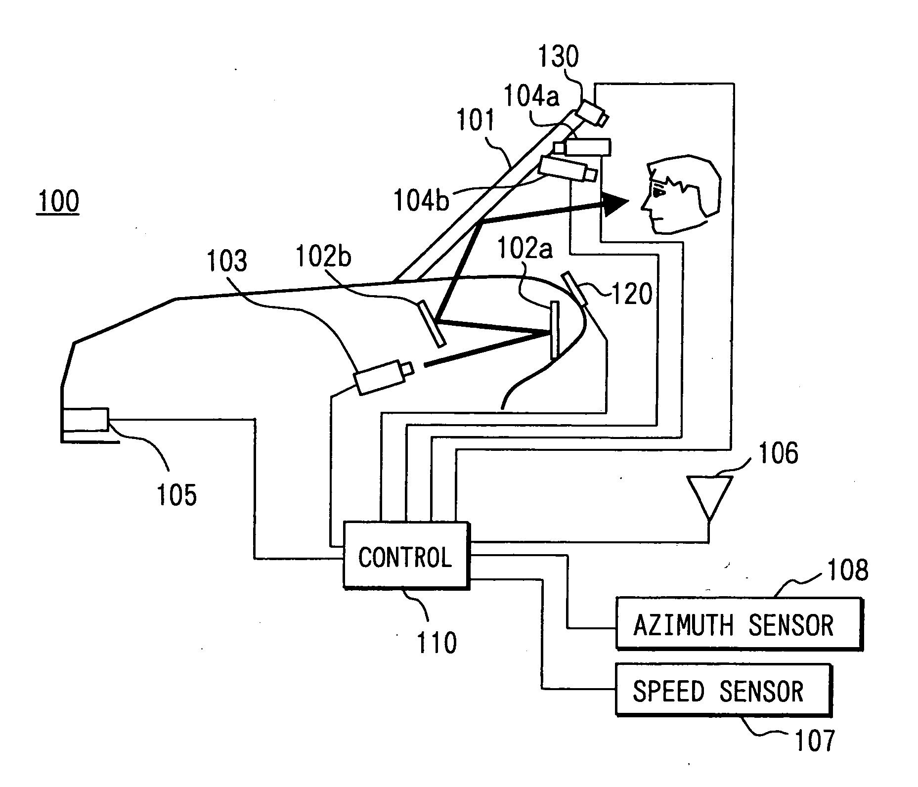
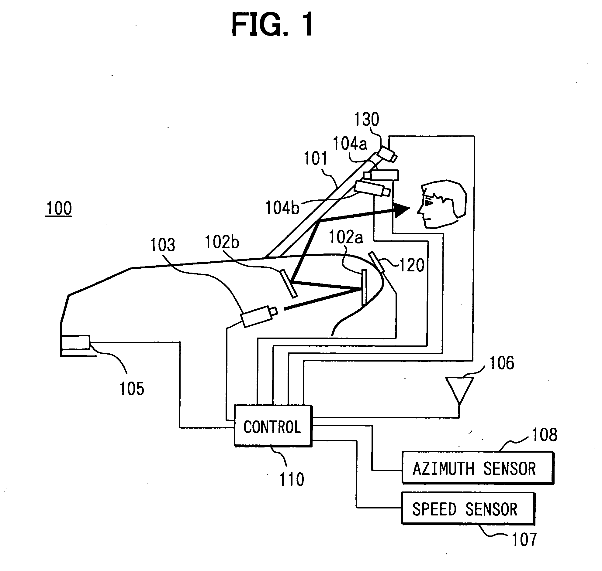
[0051] In the above embodiment, the vehicle display system 100 displays a display image for highlighting, on a display area in the windshield 101 of the subject vehicle. However, the system 100 can be differently constructed. For instance, a color image of a forward scenery ahead of the subject vehicle can be displayed on a display screen 120 (shown in FIGS. 1, 2) disposed around a center console or a head-up display having a display area defined in a part of the windshield 101 while the display image for highlighting is superimposed over the color image of the forward scenery.

[0052] This enables the user to properly recognize the brake lights of the leading vehicle, the road signs such as the halt sign, and do-not-enter sign, and the traffic control apparatus with the red traffic signal lighting, all of which mainly include “red” that indicates the information important to the driving.

modification 2

[0053] (Modification 2)

[0054] In the above embodiment, the vehicle display system 100 displays a cross-shape, as shown in FIG. 6, as a display image for highlighting. However, the display image for highlighting can be generated differently. For instance, a display image that indicates a position can be displayed with a red light element having a brightness more than that of the forward scenery. Further, as shown in FIG. 9, a display image can be displayed by magnifying the object having a red light element such as a halt sign (SG). Yet further, a display image can be displayed by blinking the position having a red light element. In this structure, the red light element is highlighted on the windshield of the subject vehicle, so that the user can be provided with the information important to the driving.

[0055] Furthermore, in the modification 1, the display image superimposed on the displayed color image of the forward scenery can be displayed so that the display image possesses a r...

modification 3

[0056] (Modification 3)

[0057] For instance, generally, viewing, in the daytime, lighting of the brake lights of the leading vehicle or lighting of the red traffic signal of the traffic control apparatus is more difficult than in the nighttime. This phenomenon remarkably takes place, in particular, when a sun light directly advances to the subject vehicle around the morning or twilight. By contrast, in the nighttime, the lighting of the brake lights of the leading vehicle or the lighting of the red traffic signal of the traffic control apparatus can be recognized without any highlighting.

[0058] Consequently, it is preferable that a display image for highlighting is preferentially provided when the brightness of the forward scenery is a given level or more. Thus, the user who is in a state where the corresponding object is difficult to be recognize is properly provided with the information important to driving.


PUM


Abstract

A vehicle display system recognizes, from within a color image of a forward scenery of a subject vehicle, an object such as left and right brake lights of a leading vehicle or a halt sign, each of which includes a red light element. Of the recognized object, a given position on a display area in a windshield of the subject vehicle is extracted. The extracted given position is then highlighted on the display area so that a user of the subject vehicle can properly recognize the object including the red light element.

Description

CROSS REFERENCE TO RELATED APPLICATIONS [0001] This application is based on and incorporates herein by reference Japanese Patent Application No. 2003-420006 filed on Dec. 17, 2003. FIELD OF THE INVENTION [0002] The present invention relates to a display system used in a vehicle including an automobile. BACKGROUND OF THE INVENTION [0003] Conventionally, there is proposed a driving assistance system that is used for indicating information relating to a periphery, to a driver of a vehicle (e.g., Patent document 1). In Patent document 1, when it is determined that a driver misses looking at a road sign, a driving assistance system designates information relating to the not seen road sign, to inform the driver of the designated information. [0004] Generally, an urban area has more road signs than a suburban area. When a driver pays attention to a pedestrian or another vehicle during the driving in the urban area, the driver cannot sufficiently observe the peripheral road signs. Here, the...

Claims


Application Information

Patent Timeline
IPC IPC(8): B60K35/00G02F1/13B60R1/00B60R11/02G06T7/00G08G1/00G08G1/09G08G1/0962G08G1/0969G08G1/16
CPCG08G1/0969G08G1/163B60K2350/2052B60K2350/2013B60K35/00B60K2370/21B60K2370/334
Inventor ISAJI, KAZUYOSHITSURU, NAOHIKOWADA, TAKAHIROKANEKO, HIROSHI
Owner DENSO CORP
Why Eureka
Try Eureka