Ultra high frequency radio frequency identification tag

a radio frequency identification and ultra high frequency technology, applied in the structural form of resonant antennas, instruments, radiating elements, etc., can solve the problems of low efficiency of electrical signal absorbed by antennas to couple to integrated circuits, low power transfer, non-uniform thickness,

Inactive Publication Date: 2005-06-23
3M INNOVATIVE PROPERTIES CO
View PDF21 Cites 157 Cited by
  • Summary
  • Abstract
  • Description
  • Claims
  • Application Information

AI Technical Summary

Benefits of technology

[0013] In another preferred embodiment of the above method, the first portion of the antenna has a first real component value and a first imaginary component value and the second portion of the antenna has a second real component value and a second imaginary component value, the second portion of the antenna is selected to provide a second real component value and second imaginary component value which assist in balancing the first real component value and the first imaginary component value to provide the second impedance value of the antenna substantially similar to the first impedance value of t...

Problems solved by technology

Under these conditions of mismatched real components and unbalanced imaginary components of the antenna and integrated circuit impedances, the electromagnetic signal absorbed by th...

Method used


Image

  • Ultra high frequency radio frequency identification tag
  • Ultra high frequency radio frequency identification tag
  • Ultra high frequency radio frequency identification tag

Examples


examples

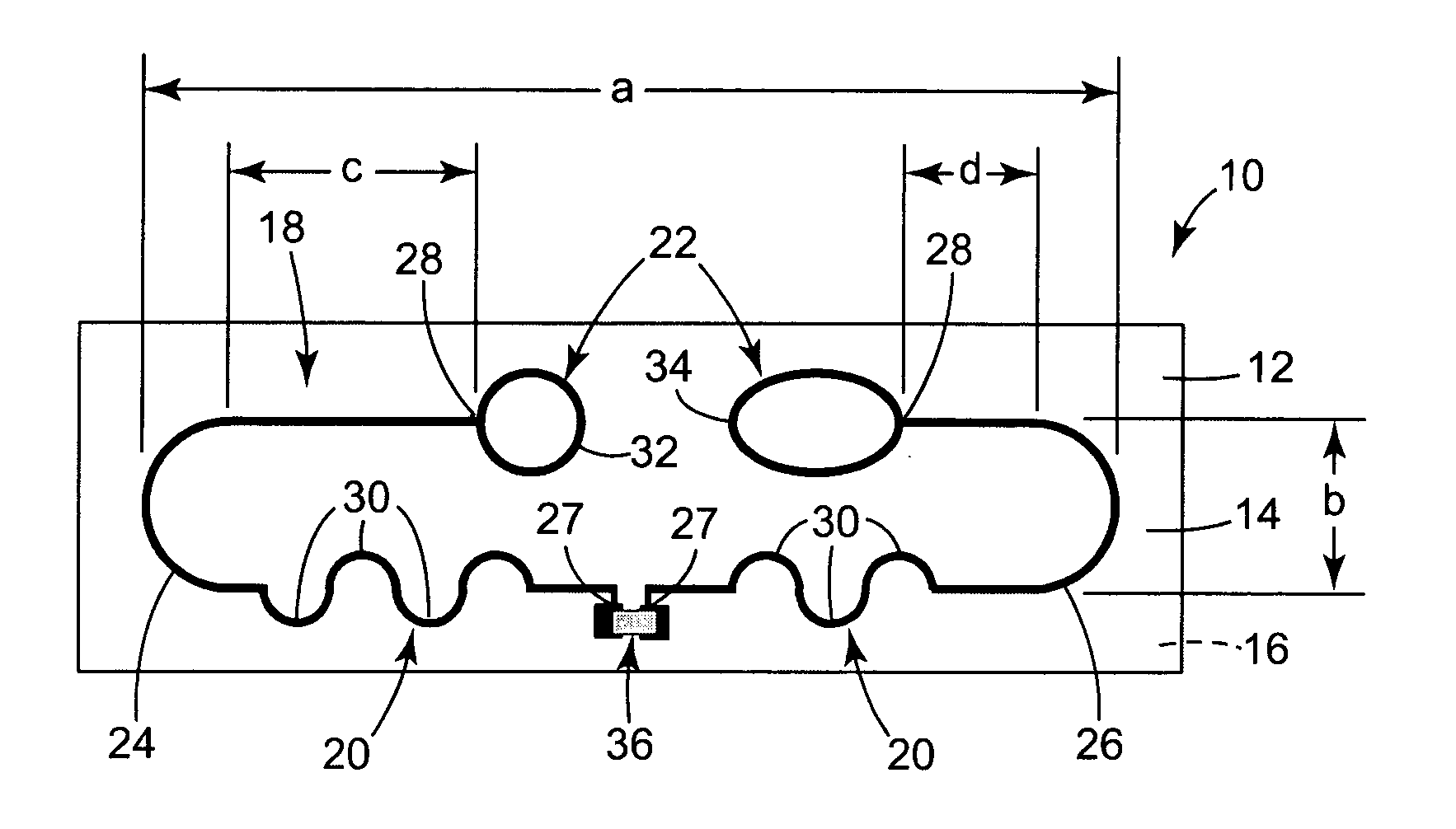
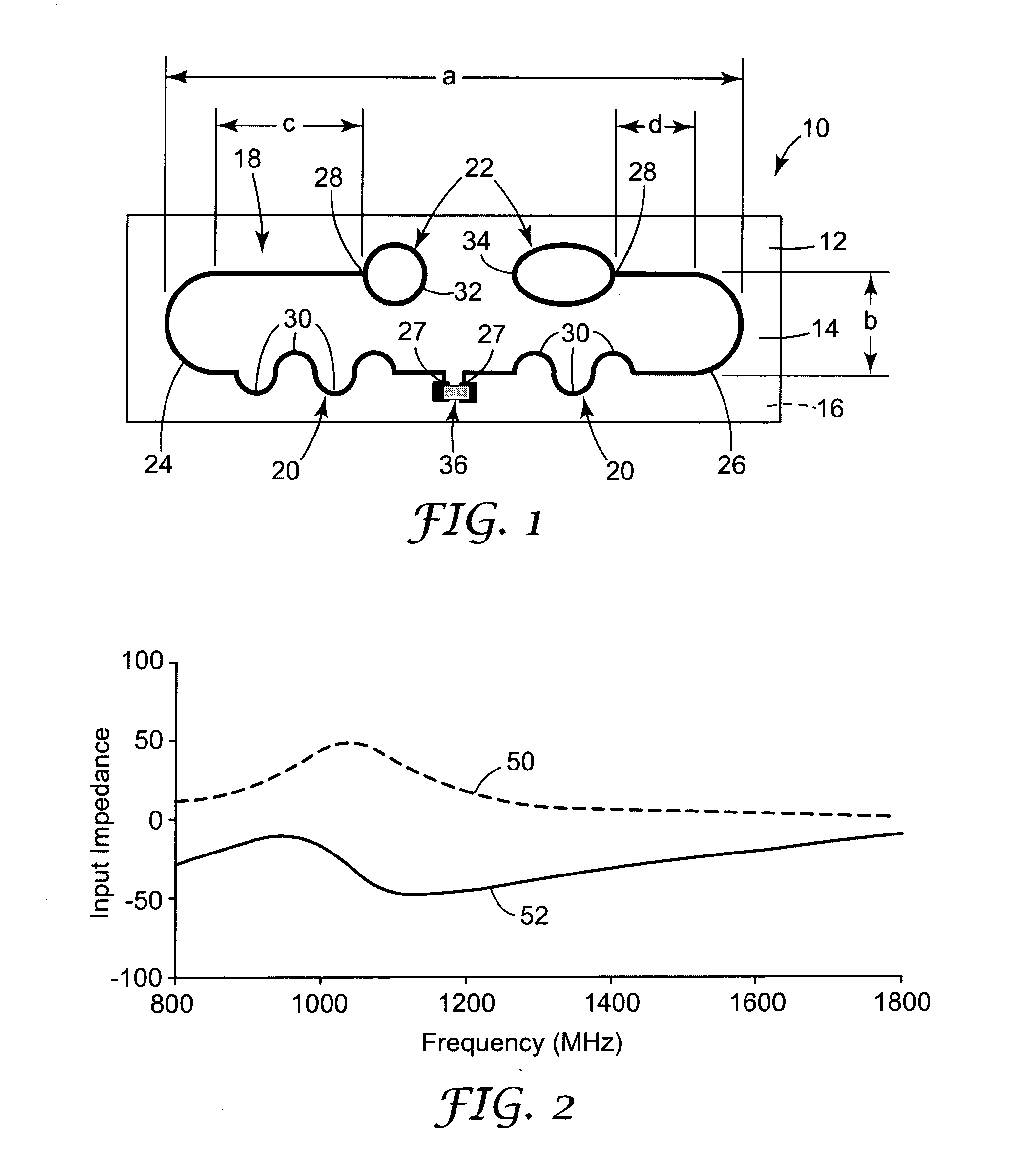
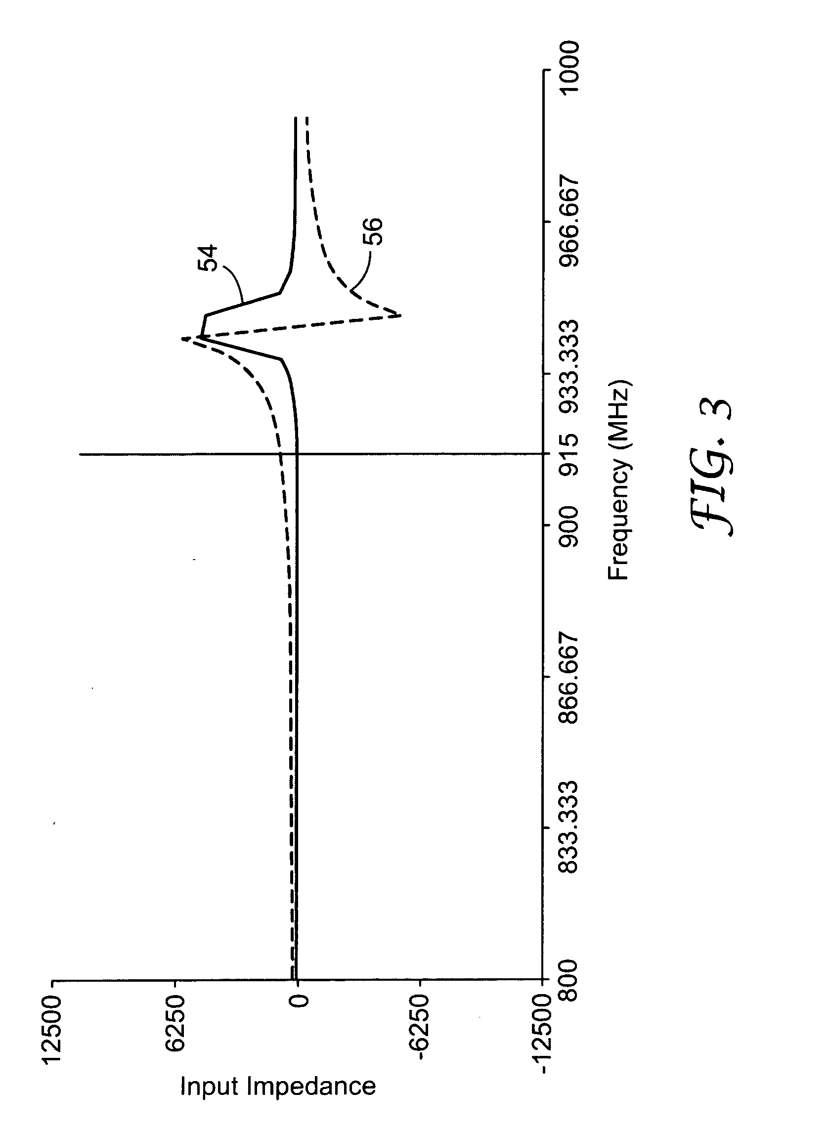
[0047] One preferred embodiment of the RFID tag 10 of the present invention was made, as illustrated in FIG. 1. The dimensions of the antenna 18 are illustrated in FIG. 1, and the antenna of this example included an “a” distance of 140 mm and a “b” distance of 10 mm. A comparative example of a prior art folded dipole antenna was also made.

[0048] The antenna 18 was made by plating 0.118 mm thickness copper on a 0.025 mm thick polyimide substrate 12 commercially available from Dupont Electronics, based in Wilmington, Del., under the trade name Kapton E film. Photoresist material commercially available from MacDermid, Inc, based in Wilmington, Del. under trade name MacDermid SF 320 was laminated to the surface of the plated copper film. The photoresist material was applied to the substrate, in the form of the desired final antenna 18.

[0049] The exposed copper was etched away, leaving copper in the pattern of the desired final antenna 18. The remaining photoresist material was strippe...


PUM


Abstract

An antenna design for radio frequency identification (“RFID”) tags. More particularly, the present invention relates to design for RFID tags particularly operating in the ultra high frequency (“UHF”) operating band.

Description

TECHNICAL FIELD [0001] The present invention relates to antenna design for radio frequency identification (“RFID”) tags. More particularly, the present invention relates to design for RFID tags particularly operating in the ultra high frequency (“UHF”) operating band. BACKGROUND OF THE INVENTION [0002] Radio frequency identification (“RFID”) has been proposed for use in a number of applications in which an RFID tag is attached to an item and subsequently interrogated or read to obtain information regarding that item. For example, U.S. Pat. Nos. 6,232,870 and 6,486,780, and PCT Publication WO 00 / 10122 describe various functions and applications for RFID systems, and exemplify the use of RFID tags in libraries. U.S. Pat. No. 5,963,134 also describes certain uses for RFID systems in libraries and for other applications. [0003] The design of a typical RFID tag reflects its origin in the semiconductor and printed circuit board industries. Although functional, the design has a number of f...

Claims


Application Information

Patent Timeline
IPC IPC(8): G06K19/07G06K19/077H01Q1/22H01Q1/38H01Q9/04H01Q9/26H01Q9/28H01Q23/00
CPCG06K19/07749G06K19/07786H01Q23/00H01Q1/38H01Q9/265H01Q1/2208G06K19/07H01Q9/04H01Q9/28
Inventor EGBERT, WILLIAM C.
Owner 3M INNOVATIVE PROPERTIES CO
Why Eureka
Try Eureka