Contact probe storage sensor pod

a technology of contact probes and sensors, applied in the field of contact probe storage systems, can solve the problems of system read performance being slower than desired, the thermal response is slower than desired, and the system's read performance is slower than desired

Inactive Publication Date: 2005-06-23
HEWLETT PACKARD DEV CO LP
View PDF48 Cites 16 Cited by
  • Summary
  • Abstract
  • Description
  • Claims
  • Application Information

AI Technical Summary

Problems solved by technology

Nevertheless, the thermal response has been found to be slower than desired and is significantly slower than the cantilever's ability to mechanically follow the data pat

Method used


Image

  • Contact probe storage sensor pod
  • Contact probe storage sensor pod
  • Contact probe storage sensor pod

Examples


first embodiment

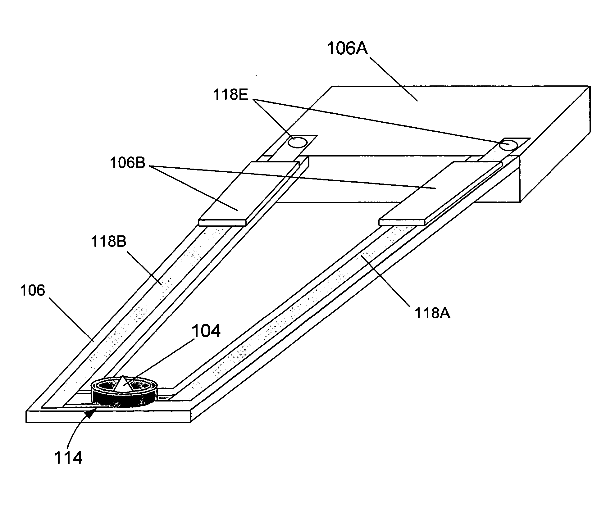
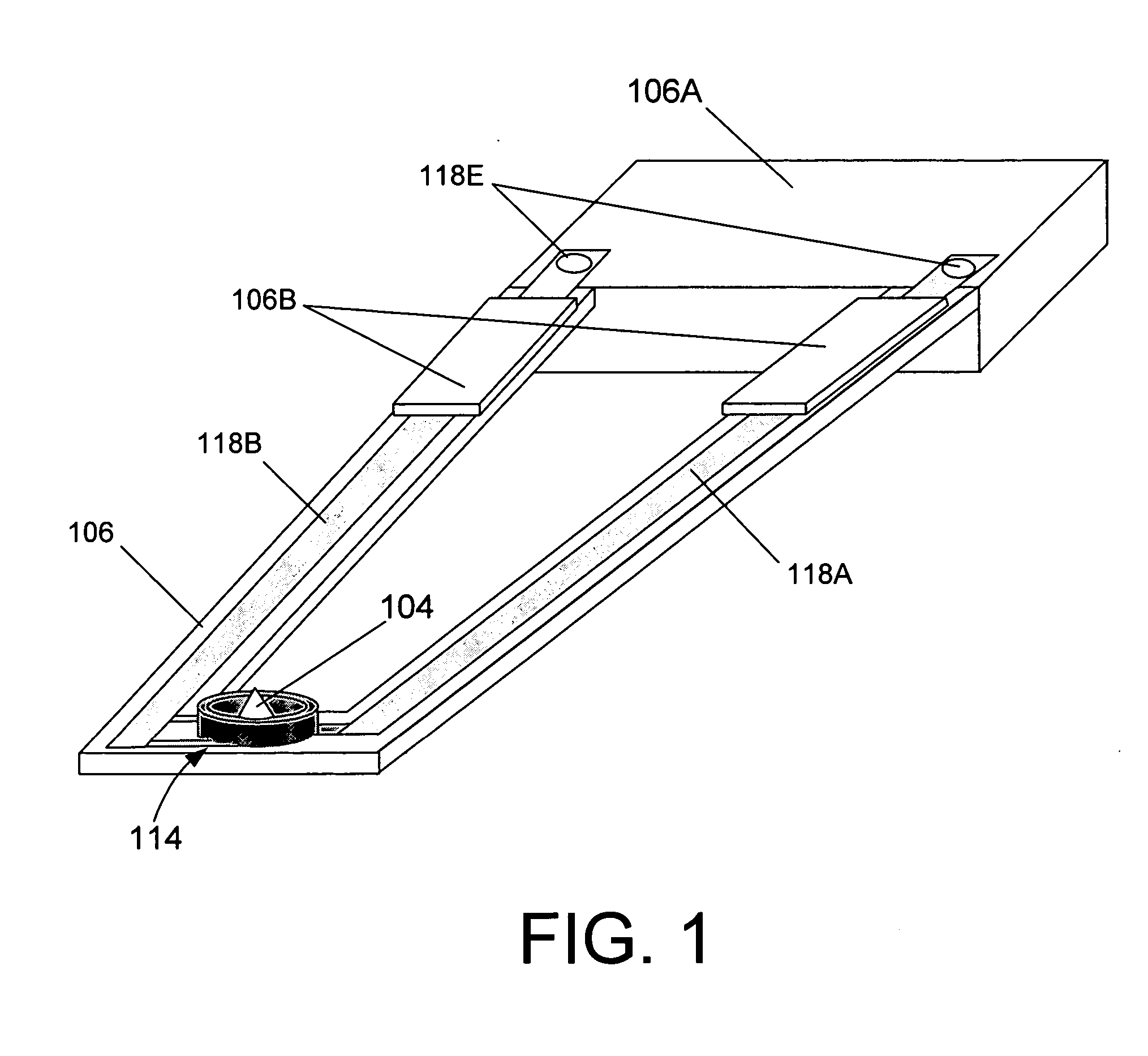
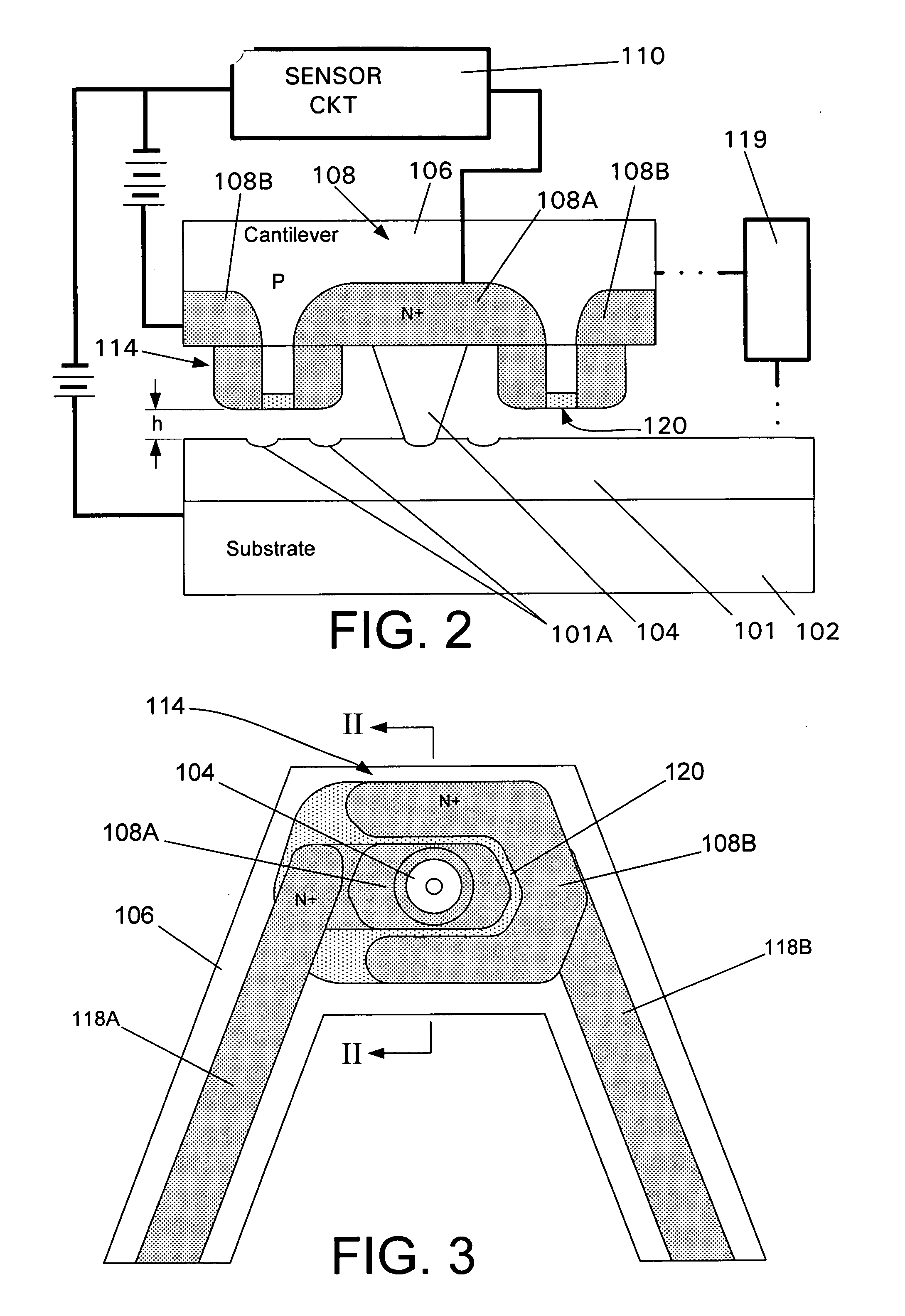
[0013]FIGS. 1-3 show the invention. FIG. 2 shows a suitable medium 101 such as a layer of polycarbonate or polymethylmethacrylate (PMMA) for example, which is formed over the surface of a suitable support substrate 102. The media 101, which in this case is non-conductive, has been heated (for example) locally to write data by forming a change in medium topography which can be detected by lowering a probe 104, which is formed at the end of the cantilever 106 in the manner depicted in FIG. 1, onto the medium.

[0014] Although the topography is shown as comprising a series of data recesses or pits 101A, these can be replaced with humps (not shown) or a combination of pits and humps. However, it should be noted that these humps (if used) should be isolated from the pits so as not to be not confused with the raised ring that tends to form around the mouth of the pits like a lunar impact crater.

[0015] Thus, when the medium 101 or the cantilever 106 has been moved relative to the other to a...

second embodiment

[0030] the invention is shown in FIGS. 4 and 5. In this embodiment the FET 108 which is shown in FIGS. 1 and 2 is replaced with sensor elements 116 which juxtapose the medium 101 and which are circuited with the sensor circuit 110 so that a variable, which varies with the variation in the gap between the sensor elements 116 and the media 101, is monitored.

[0031] In this second embodiment, the sensor elements 116 comprise heated elements which are heated via the passage of current therethrough and thus responsive to the change in distance between the media 101 and the cantilever 106. The juxtaposed disposition of the sensing elements 116 at the end of the pod represents an improvement over the arrangements discussed in the opening paragraphs of this disclosure, in that, due to their reduced distance from the medium, the sensing elements 116 are exposed to conditions which render them more responsive in that the amount of heat which is removed from the heated elements is increased and...


PUM


Abstract

An embodiment of a read mechanism used in a contact atomic resolution storage system, has a cantilever disposed with a medium which is movable relative to the cantilever. The cantilever has a probe which extends from the cantilever and which contacts a surface of the medium. A pod is formed on a side of the cantilever facing the medium and extends toward the media. A sensor element is formed on the pod so as to juxtapose the medium.

Description

BACKGROUND OF THE INVENTION [0001] The present invention relates generally to a Contact Probe Storage System (CPS) arrangement and more specifically to a sensor arrangement for use with a CPS which exhibits improved response. [0002] It has been hitherto been proposed to sense data which is written onto a movable medium using a probe that is supported on a cantilever and used to contact the medium. By using heat transfer characteristics between the movable medium and the probe (or a portion of the cantilever), it is possible to determine minute changes in distance between the movable medium and the cantilever on which the probe is carried, and use this as a means for reading out the data stored on the movable medium. [0003] In the above type of arrangement, both imaging and reading are carried out using a thermomechanical sensing concept. The heater in the cantilever that is used only for writing is also used as a thermal readback sensor by exploiting a temperature-dependent resistan...

Claims


Application Information

Patent Timeline
IPC IPC(8): G01Q60/32G01Q60/58G01Q80/00G11B9/00G11B11/06G11B11/08G11B13/00
CPCB82Y10/00B82Y35/00G01Q60/58G11B9/14G11B9/1409G11B2005/0021G11B9/1445G11B11/06G11B11/08G11B13/00G11B9/1418
Inventor MEJIA, ROBERT GUIDO
Owner HEWLETT PACKARD DEV CO LP
Why Eureka
Try Eureka