
DDS circuit with arbitrary frequency control clock

a technology of arbitrary frequency control and clock, which is applied in the direction of synchronisation signal speed/phase control, instruments, generating/distributing signals, etc., can solve the problem of not being able to arbitrarily set the frequency of clksub>a

Active Publication Date: 2005-06-23
TERADYNE
View PDF14 Cites 11 Cited by
  • Summary
  • Abstract
  • Description
  • Claims
  • Application Information

AI Technical Summary

Benefits of technology

[0019] In a preferred embodiment, the DDS circuit is used in automatic test equipment having central control circu...

Problems solved by technology

Because the frequency of waveform Fout is influenced by the frequency of CLKACC, it is not possible to arbitrarily set the frequency of CLKACC.
A difficulty arises because the DDS circuit is clocked by clock CLKACC.

Method used


Image

  • DDS circuit with arbitrary frequency control clock
  • DDS circuit with arbitrary frequency control clock
  • DDS circuit with arbitrary frequency control clock

Examples


Embodiment Construction

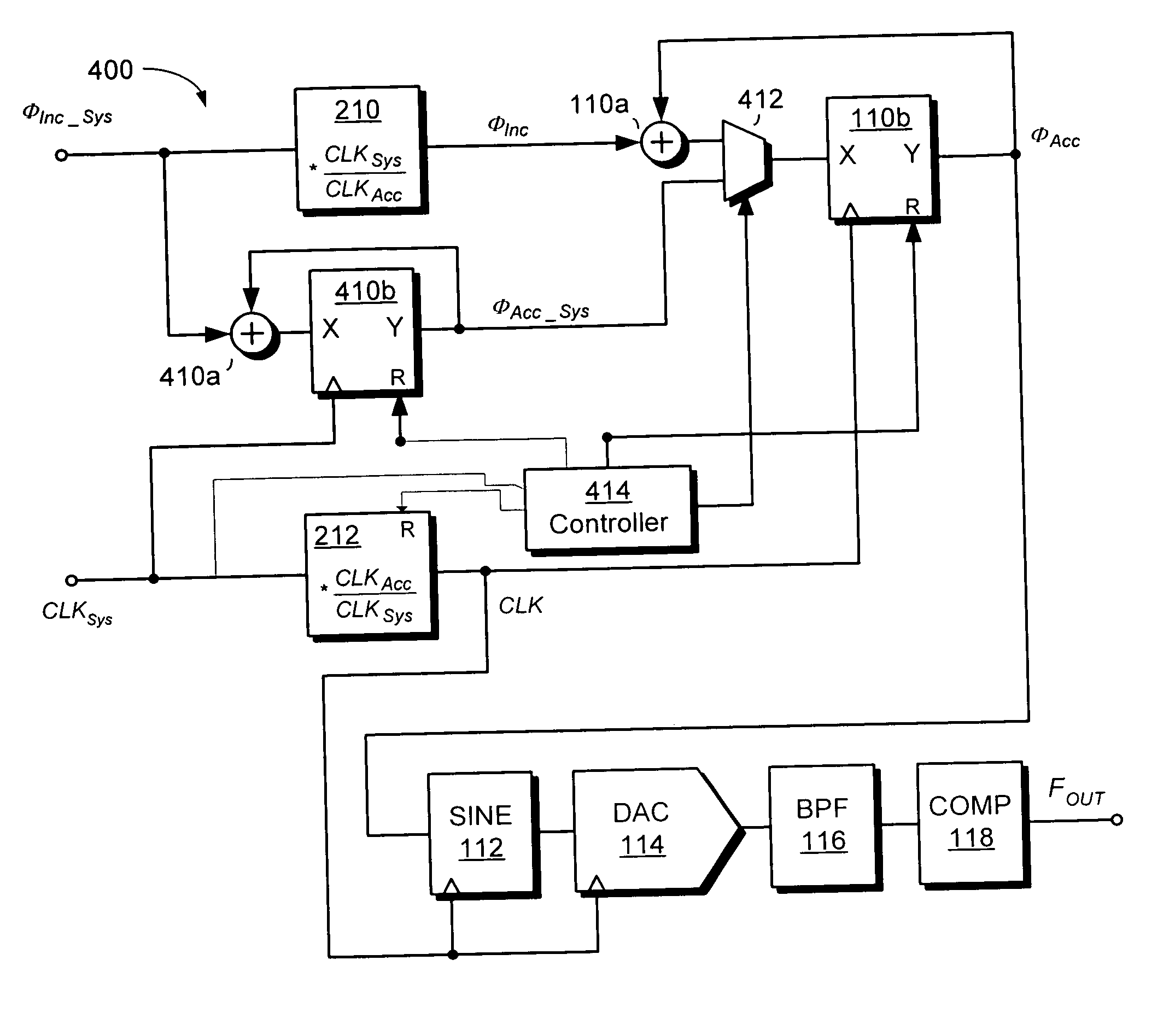
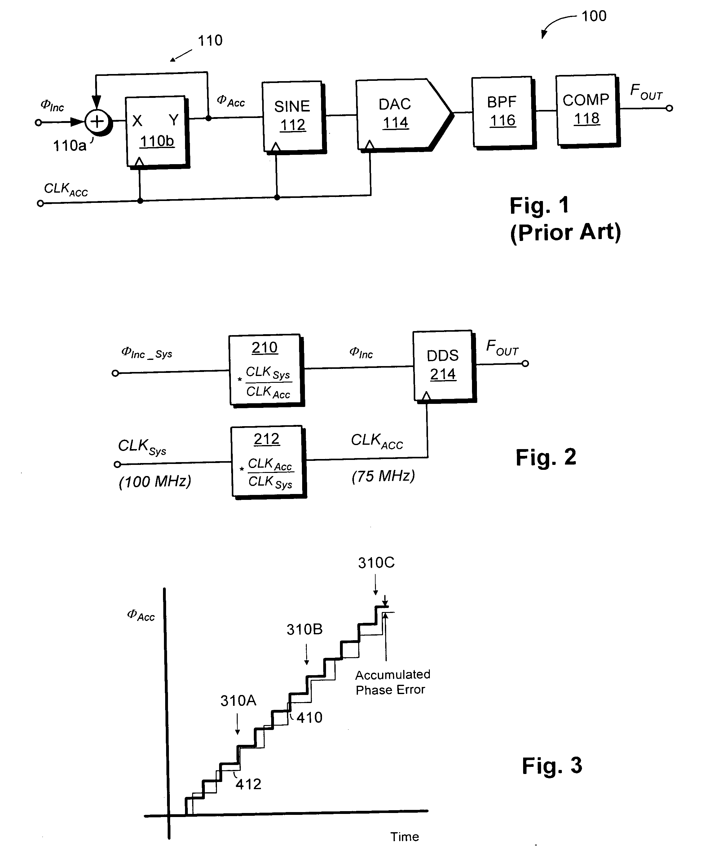
[0027]FIG. 2 shows simplified block diagram of a digital synthesis circuit operating in a system that uses a different frequency than the DDS circuit. DDS 214 generates FOUT. DDS 214 may be a DDS circuit such as is shown in the prior art. Alternatively, DDS 214 may be a circuit as shown in my copending patent application entitled HIGH RESOLUTION SYNTHESIZER WITH IMPROVED SIGNAL PURITY, filed on the same date as this application, which is hereby incorporated by reference. Regardless of the precise construction of DDS 214, the frequency at which DDS 214 is clocked influences the frequency of FOUT.

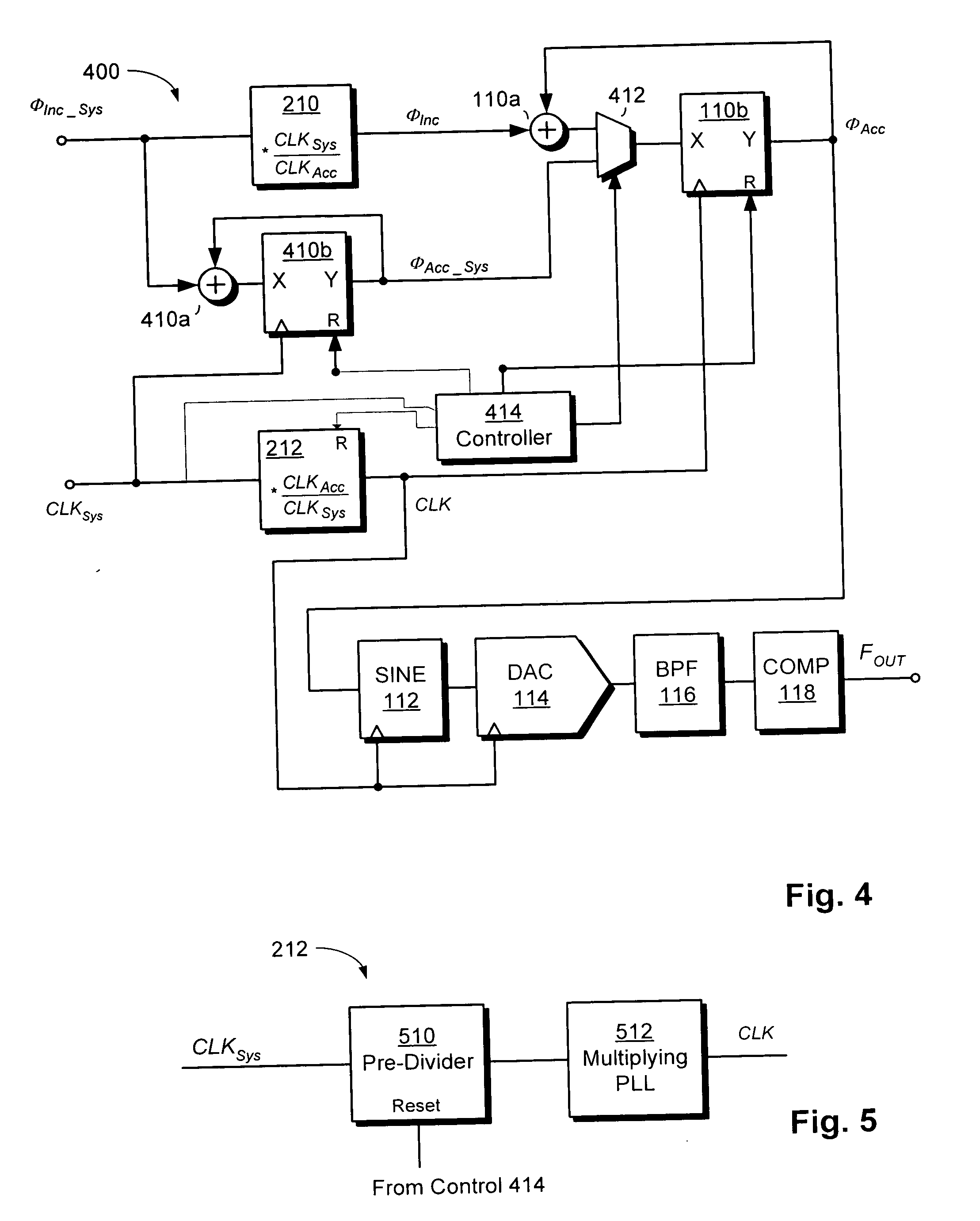
[0028] DDS 214 is clocked by clock CLKACC. The frequency of CLKACC is, for purposes of illustration, 75 MHz. The actual frequency will depend on the desired characteristics of FOUT. Also, as will be described below, CLKACC is generated by frequency multiplier 212. Because frequency multiplier 212 has finite precision, CLKACC might not have exactly the desired frequency. Accordingly, CLKACC “...


PUM


Abstract

A test system using direct digital synthesis for generation of a spectrally pure, agile clock. The clock is used in analog and digital instruments in automatic test system. A DDS circuit is synchronized to the tester system clock because it is clocked by a DDS clock generated from the system clock. Accumulated phase error is reduced through the use of a parallel accumulator that tracks accumulated phase relative to the system clock. At coincidence points, the accumulated phase in the DDS accumulator is reset to the value in the system accumulator.

Description

[0001] This invention relates generally to signal generation and more specifically to generation of periodic signals in a flexible manner. BACKGROUND OF THE INVENTION [0002] Direct Digital Synthesis (“DDS”) is a technique used to generate periodic signals where control over one or more signal properties is desired. Analog signals can be generated with either the period or the wave shape controlled through DDS. [0003]FIG. 1 shows a traditional DDS architecture with DDS 100 being used to generate a sine wave that is then converted to a two-valued clock. DDS 100 receives an accumulator clock CLKACC and a digital input signal ΦInc indicating a phase increment. The DDS outputs a signal FOUT. The frequency of FOUT can be set by varying the frequency of CLKACC and / or varying the phase increment ΦInc. [0004] In operation, accumulator 110 produces a new output value ΦAcc on each cycle of CLKACC. To produce each new value, the accumulator 110 adds ΦInc to its current contents. As shown in FIG...

Claims


Application Information

Patent Timeline
IPC IPC(8): G06F1/08G01R31/00G01R31/28G01R31/3167G06F1/03H03L7/00
CPCH03L7/00G06F1/0328
Inventor MESSIER, JASON
Owner TERADYNE
Learn More