

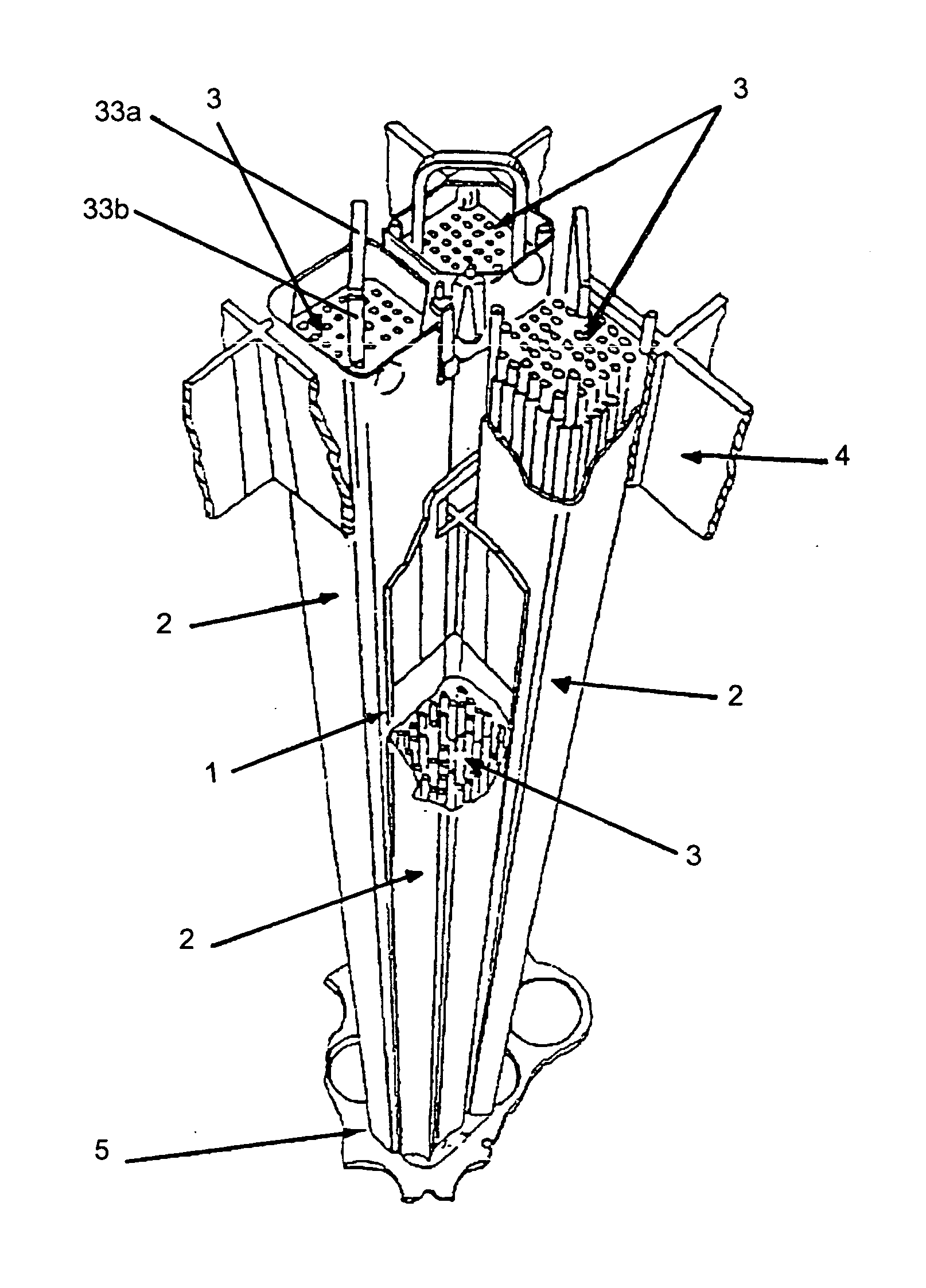
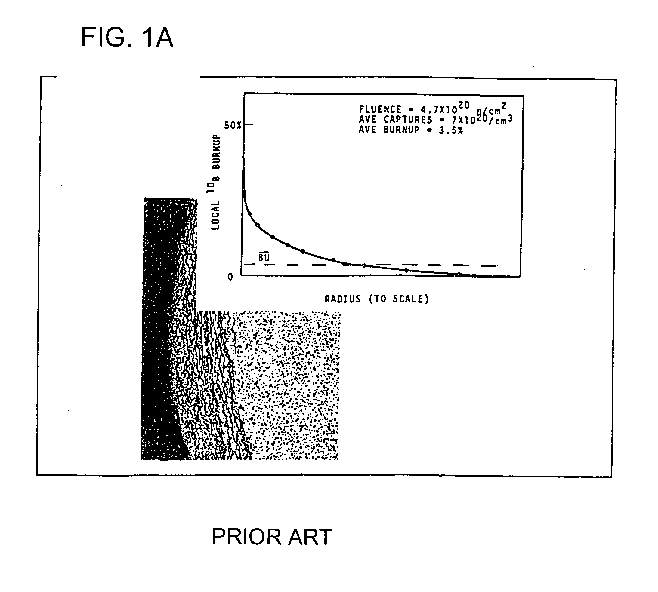
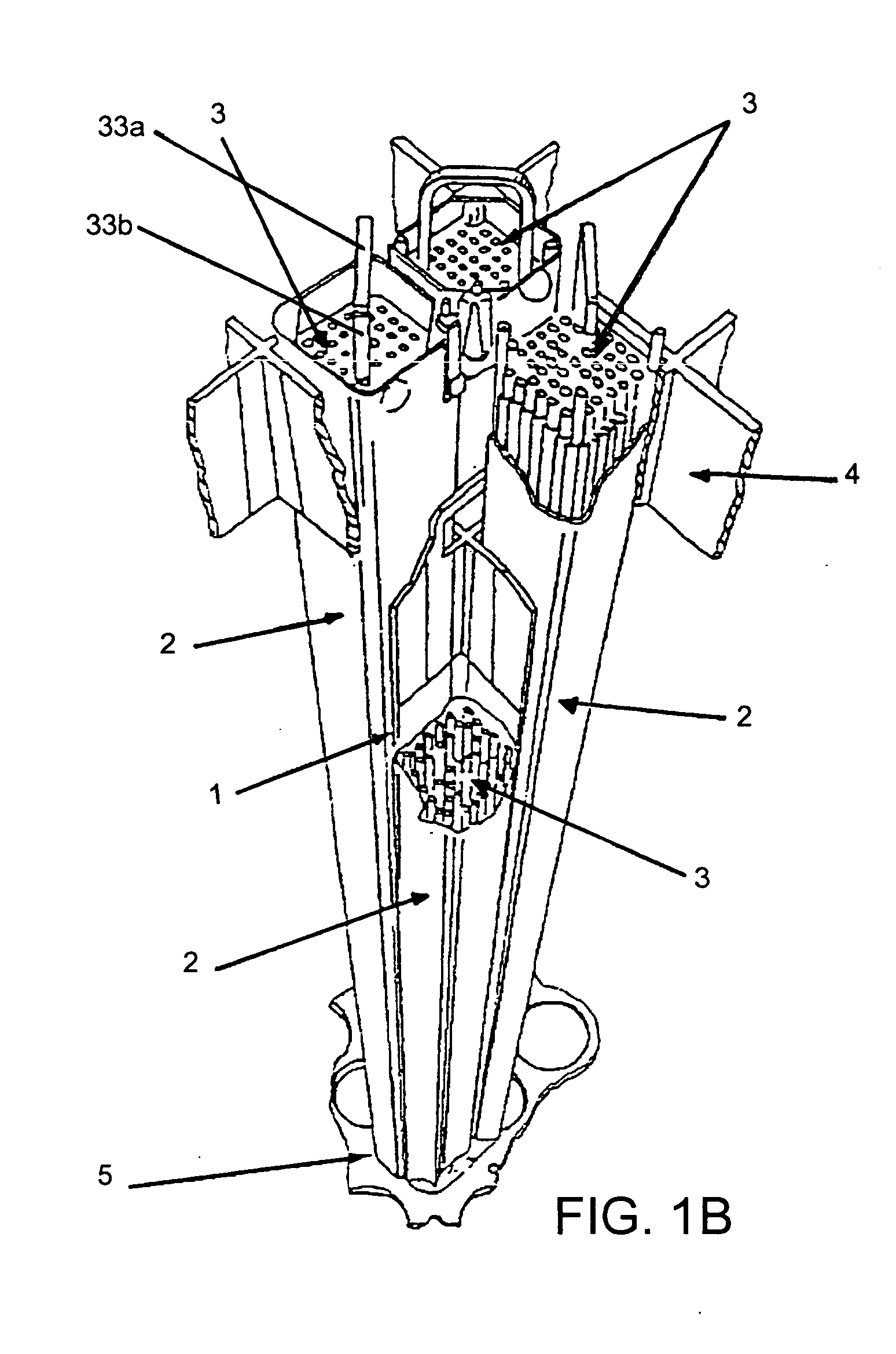
Control element for a nuclear reactor
a control element and nuclear reactor technology, applied in reactor fuel elements, climate sustainability, nuclear energy generation, etc., can solve the problem that the absorber enclosure cannot be swollen and swollen, and achieve the effect of reducing the theoretical density of smeared liquid, preventing initial swelling of the absorber, and high burn up percentage am of the employed absorber material
- Summary
- Abstract
- Description
- Claims
- Application Information
AI Technical Summary
Benefits of technology
Problems solved by technology
Method used
Image

Examples
Embodiment Construction
[0059] In the following description, numerous specific details are set forth. However, it is understood that embodiments of the invention may be practiced without these specific details. In other instances, well-known structures and techniques have not been shown in detail in order not to obscure the understanding of this description.
[0060] Reference in the specification to “one embodiment” or “an embodiment” means that a particular feature, structure, or characteristic described in connection with the embodiment is included in at least one embodiment of the invention. The appearances of the phrase “in one embodiment” in various places in the specification do not necessarily all refer to the same embodiment.
[0061] Although the invention is illustrated and described herein as embodied in “Control Element for a Nuclear Reactor”, the present invention is nevertheless not intended to be limited to the details shown or described, since various modifications and structural changes may b...
PUM
 Abstract
Description
Claims
Application Information