Collimator for a computer tomograph

a computer tomograph and collimator technology, applied in the field of collimator for computer tomographs, can solve problems such as rigidity reduction, and achieve the effect of high accuracy in positioning of collimator plates and simple production

Inactive Publication Date: 2005-06-23
SIEMENS HEALTHCARE GMBH
View PDF6 Cites 32 Cited by
  • Summary
  • Abstract
  • Description
  • Claims
  • Application Information

AI Technical Summary

Benefits of technology

[0010] This configuration is based on the idea of abandoning the configuration of continuous, elongated cutouts or slots for the collimator plates and, instead, of constructing in a fashion distributed over the length of a collimator plate a number of discrete tabs or tongues spaced apart from one another as well as, in a fashion complimentary thereto, individual and discrete cutouts in the holder. The cutouts for positioning the individual collimator plates therefore do not extend over the entire length. Rather, it is now only short segments in the holder that have material windows. These windows or cutouts can be positioned in a highly accurate fashion with a low outlay. In particular, a substantially higher stability is thereby achieved and the short cutouts are surrounded by a comparatively large material wall.
[0011] In accordance with an expedient development, the tab receptacles of two neighboring collimator plates are arranged offset from one another. In this case, the tab receptacles of neighboring collimator plates preferably do not overlap one another. The result of this is that the material weakness caused by the cutouts, and the reduction in rigidity are kept low, since the cutouts are spaced apart as far as possible from one another by their offset arrangement. The overall result of this is to enable a holder with a high intrinsic rigidity and a high positionally accurate construction of cutouts.
[0012] The holder expediently includes an upper collimator part and a lower collimator part in which the tab receptacles are respectively arranged. Collimator plates are therefore clamped between two housing parts with the respective tab receptacles. This permits simple mounting while simultaneously ensuring high positional accuracy.
[0017] In accordance with a preferred development, the tabs reach through the holder. This measure renders it possible for the tabs, that is to say the collimator plates themselves, to participate in the exact positioning of the collimator on an assigned sensor element.
[0018] The collimator plates expediently have a length of >40 mm, in particular a length of approximately 60 mm. Even in the case of this relatively large length of the collimator plates, a highly accurate positioning of the collimator plates is enabled even given a relatively thin-walled construction of the holder owing to the particularly offset arrangement of the individual, discrete tab receptacles. The holder is expediently a plastic injection-molded part for the purpose of simple production.

Problems solved by technology

The result of this is that the material weakness caused by the cutouts, and the reduction in rigidity are kept low, since the cutouts are spaced apart as far as possible from one another by their offset arrangement.

Method used


Image

  • Collimator for a computer tomograph
  • Collimator for a computer tomograph
  • Collimator for a computer tomograph

Examples


Embodiment Construction

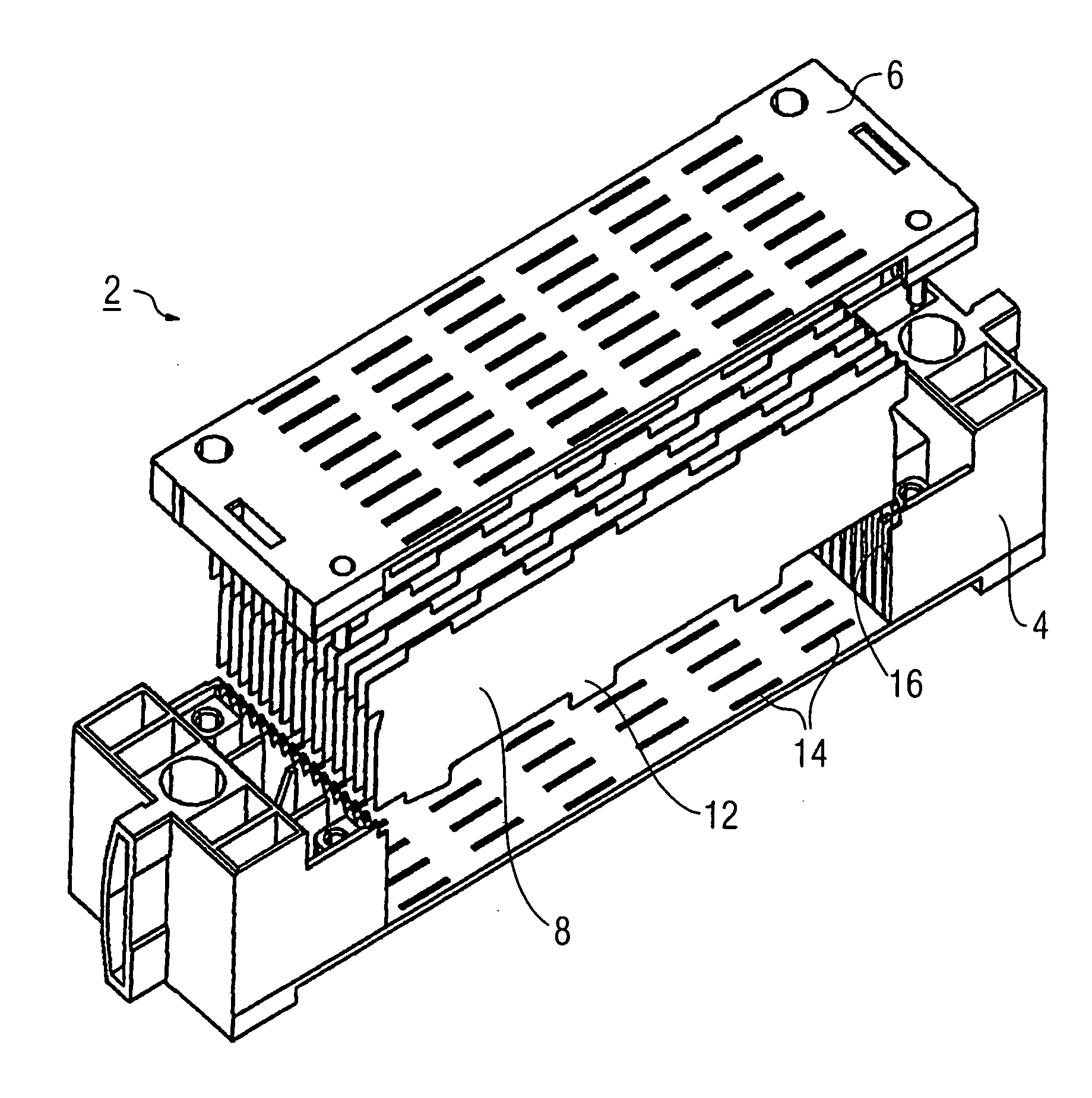
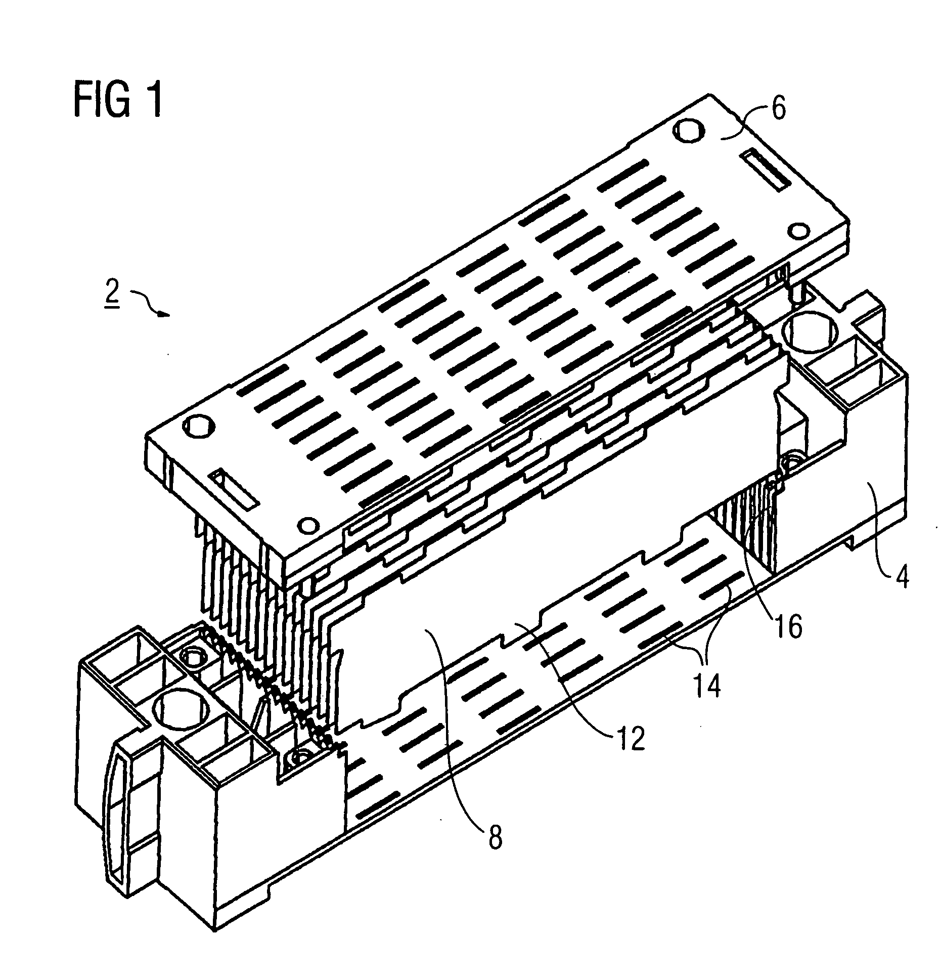
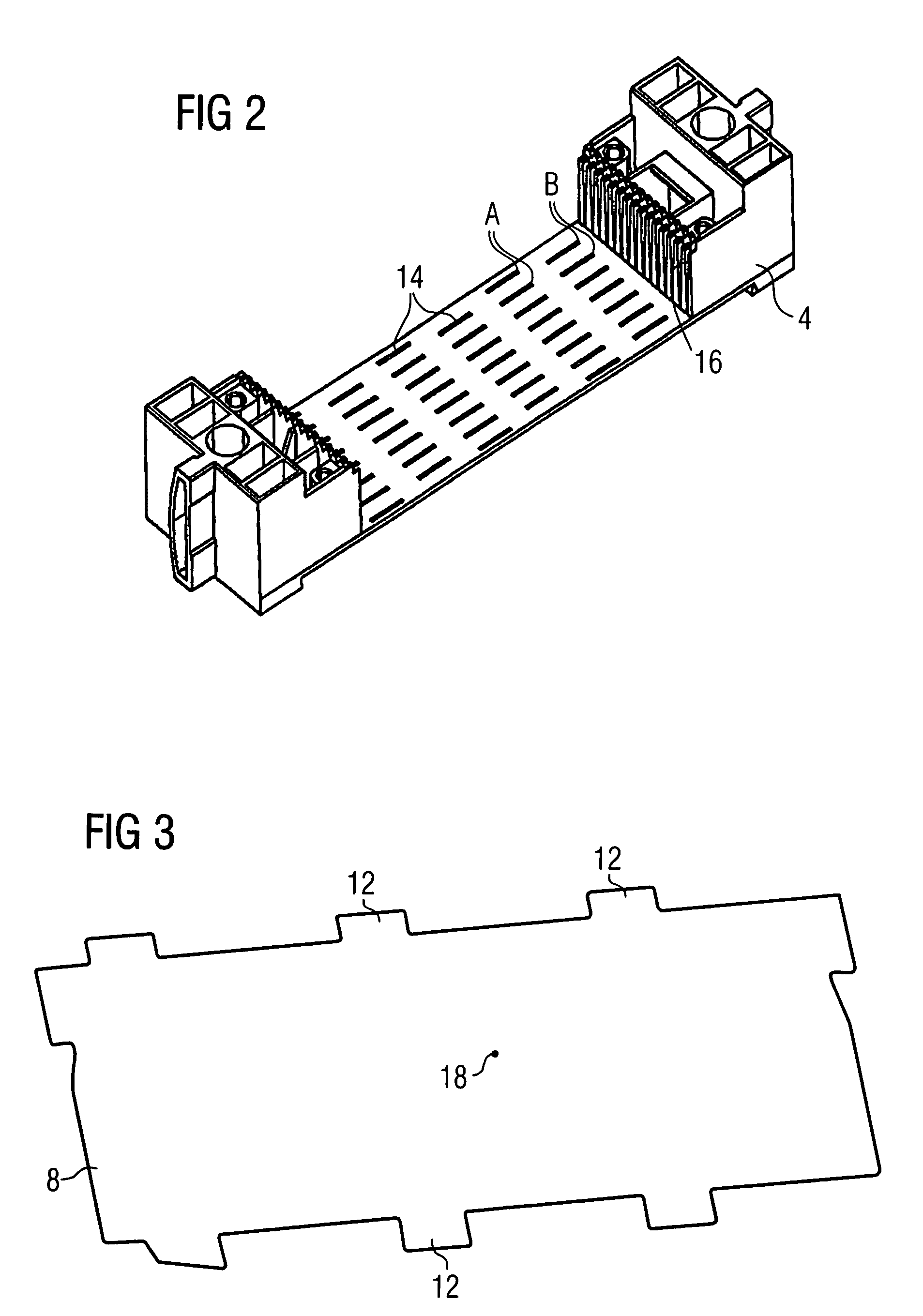
[0025] A collimator 2 in accordance with FIGS. 1 to 3 includes a lower collimator part 4, an upper collimator part 6 and a plurality of sheet-like collimator plates 8 that are arranged approximately parallel to one another and arranged in the shape of a fan relative to a beam focus of an X-ray source. The lower collimator part 4 and the upper collimator part 6 form a holder for the collimator plates 8 and are connected to one another in the assembled state in the manner of two housing parts.

[0026] The collimator plates 8 must be positioned very exactly in the collimator 2. In order to ensure a highly accurate positioning even with very elongated collimator plates 8, which are approximately 60 mm long in the exemplary embodiment, individual tabs 12 are constructed at the edge of the long sides on each of the collimator plates 8. These tabs project in the manner of tongues from the long sides. The individual tabs 12 from the respective long side are spaced apart from one another at u...


PUM


Abstract

A collimator for a computer tomograph includes a number of collimator plates and a holder for the collimator plates. The collimator plates include, at the edge, a number of tabs spaced apart from one another. In a fashion corresponding to this, the holder has receptacles that are assigned to the tabs and that are spaced apart from one another, into which the tabs of the collimator plates engage. This configuration ensures highly accurate positioning of even long collimator plates.

Description

[0001] The present application hereby claims priority under 35 U.S.C. §119 on German patent application number DE 103 61 510.5 filed Dec. 23, 2003, the entire contents of which are hereby incorporated herein by reference. FIELD OF THE INVENTION [0002] The invention generally relates to a collimator for a computer tomograph including a number of collimator plates and a holder for the collimator plates. BACKGROUND OF THE INVENTION [0003] A collimator or scattering collimator is to be gathered, for example, from DE 100 11 877 C2. The collimator is arranged in a detector arrangement of a computer tomograph. The collimator plates are arranged here in a radial direction relative to an X-radiation source of the computer tomograph, and serve to reduce or suppress scattered radiation that deviates from the radial direction, and is thus not aligned in a radial direction relative to the radiation source. [0004] Collimators and computer tomographs with built-in collimators are further to be gat...

Claims


Application Information

Patent Timeline
Patent Type & Authority Applications(United States)
IPC IPC(8): A61B6/03G21K1/02H05G1/02
CPCG21K1/025
Inventor FREUND, ANDREASPOHAN, CLAUS
Owner SIEMENS HEALTHCARE GMBH
Why Eureka
Try Eureka