Fastener for application to a threaded stud

a technology of threaded studs and fasteners, which is applied in the direction of threaded fasteners, screws, fastening means, etc., can solve the problems of increasing the radial clamping force and the difficulty of turning the fastener, so as to improve the ease of use of the fastener, the effect of high retention or pull-off force and no resistan

Inactive Publication Date: 2005-06-23
NEWFREY
View PDF29 Cites 14 Cited by
  • Summary
  • Abstract
  • Description
  • Claims
  • Application Information

AI Technical Summary

Benefits of technology

[0006] The object is attained by the invention in that there are arranged, on the flange and on the end of the clamping sleeve facing the flange, coupling elements and mating coupling elements that interlock when the clamping sleeve is located on the clamping element in the assembled state, and that prevent rotation of the clamping sleeve relative to the clamping element.
[0013] According to another suggestion of the invention, the clamping sleeve can be joined to the clamping element as a single piece by means of a predetermined breaking point. Manufacture of the clamping sleeve and clamping element, for example of plastic, can thus be accomplished in a single mold, and both parts are always guaranteed to be available at installation. It is advantageous for the predetermined breaking point to be located between the rearward end of the clamping element and the forward end of the clamping sleeve in the direction of installation. At installation, after placement of the clamping element on the threaded stud, an impact in the direction of the stud axis separates the clamping sleeve from the clamping element and simultaneously moves it into the installed position. This process makes possible a short installation time and can be performed equally well by hand or with the aid of automatic assembly devices.

Problems solved by technology

Because of the resilience of the wall sections, this leads to an increase in the radial clamping force, thus making it more difficult to turn the fastener.

Method used


Image

  • Fastener for application to a threaded stud
  • Fastener for application to a threaded stud
  • Fastener for application to a threaded stud

Examples


Embodiment Construction

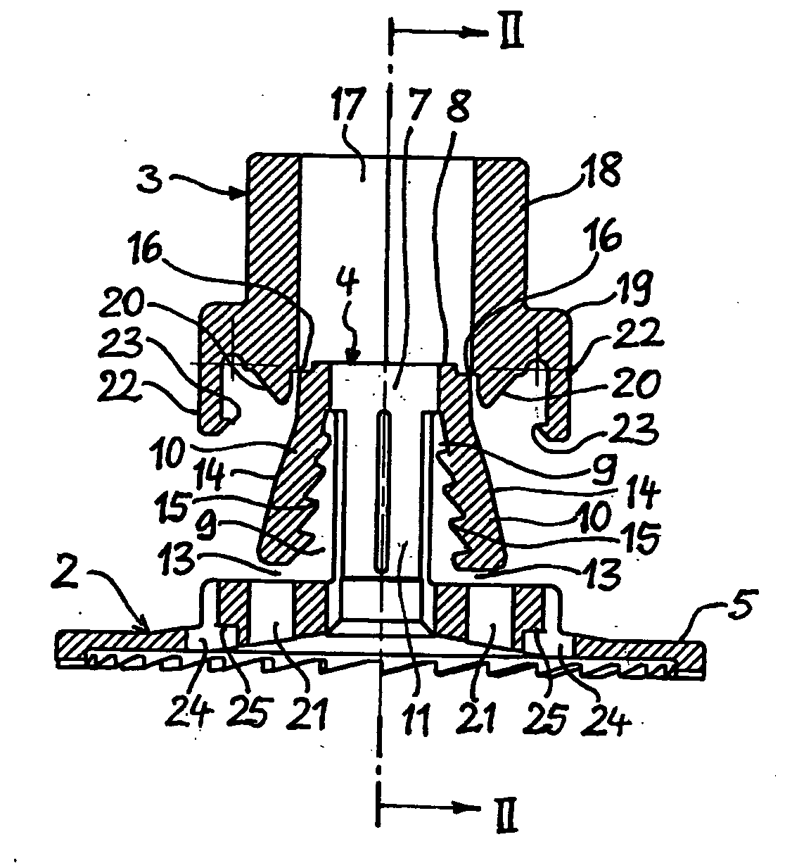
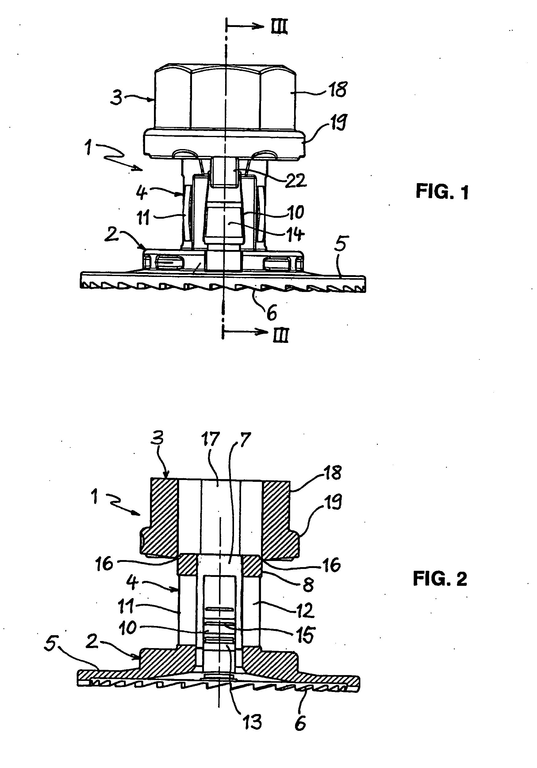
[0019] The fastener 1 shown in the drawings is made of plastic in a single piece and comprises a clamping element 2 and a clamping sleeve 3. The clamping element 2 has a sleeve-shaped section 4 and a plate-shaped flange 5 located on one end of the section 4. The flange 5 has, on the outside edge of its side facing away from the section 4, saw-tooth-like toothing 6. The teeth in the toothing 6 are oriented such that, when in contact with a mating surface, they increase the resistance to rotation in the direction in which the fastener located on a threaded stud can be unscrewed.

[0020] The clamping element 2 has a cavity 7 to accommodate a threaded stud. The cavity 7 is composed essentially of a cylindrical bore that passes through the section 4 and the flange 5, wherein the center axis of the bore coincides with the longitudinal axis of the clamping element 2. The section 4 of the clamping element 2 forms a closed ring 8 at its end opposite the flange 5. Between the ring 8 and the fl...


PUM


Abstract

Described here is a fastener (1) to be applied to a threaded stud with a sleeve-like clamping element (2) that has a cavity (7) extending in the direction of its longitudinal axis to accommodate the threaded stud and at least one clamping region (10) that can deform into the cavity (7) and that forms at least one clamping ramp (14) inclined toward the longitudinal axis on the outside of the clamping element (2). A clamping sleeve (3) can be pushed onto the clamping element and in the installed state grips around the clamping element, wherein an inner surface of the clamping sleeve (3) works together with the clamping ramp (14) such that the clamping region (10) reaches a clamping position that is deformed into the cavity (7) and holds the threaded body. The clamping element (2) has, at its forward end in the direction of installation, a flange (5). On the flange (5) and on the end of the clamping sleeve (3) facing the flange (5), there are arranged coupling elements and mating coupling elements that interlock and prevent rotation of the clamping sleeve (3) relative to the clamping element (2) when the clamping sleeve (3) is located on the clamping element (2) in the assembled state.

Description

CROSS-REFERENCE TO RELATED APPLICATIONS [0001] This application claims the benefit of German Patent Application No. 10357024.1, filed Dec. 3, 2003. The disclosure of the above application is incorporated herein by reference. FIELD OF THE INVENTION [0002] The invention concerns a fastener to be applied to a threaded stud with a sleeve-like clamping element that has a cavity extending in the direction of its longitudinal axis to accommodate the threaded stud and at least one clamping region that can deform into the cavity and that forms at least one clamping ramp inclined toward the longitudinal axis on the outside of the clamping element, and with a clamping sleeve that can be pushed onto the clamping element and in the installed state grips around the clamping element, wherein an inner surface of the clamping sleeve works with the clamping ramp such that the clamping region reaches a clamping position that is deformed into the cavity and holds the threaded body, wherein the clamping...

Claims


Application Information

Patent Timeline
Patent Type & Authority Applications(United States)
IPC IPC(8): F16B37/08F16B5/00F16B39/02
CPCF16B37/0864
Inventor REINDL, JOHANN
Owner NEWFREY
Why Eureka
Try Eureka