Connector

a technology of connecting pins and connectors, applied in the direction of coupling contact members, coupling device connections, coupling/disassembly parts, etc., can solve the problems of unstable contact between contacts and boards, difficult operation, and inability to more reduce the height of connectors, etc., to achieve stable connection

Active Publication Date: 2005-06-23
DDK LTD
View PDF2 Cites 24 Cited by
  • Summary
  • Abstract
  • Description
  • Claims
  • Application Information

AI Technical Summary

Benefits of technology

[0014] It is an object of the invention to provide an improved connector which overcomes the above problems of the prior art and which can achieve stable connection between contacts and a flexible printed circuit board or flat cable without obliquely inserting the contacts into the housing of the connector.
[0020] (1) According to the invention, the connector to be detachably fitted with a flexible printed circuit board or a flexible flat cable comprises a required number of contacts having a contact portion to contact the flexible printed circuit board or flexible flat cable, a housing for holding and fixing therein the contacts and having a fitting opening for inserting the flexible printed circuit board or flexible flat cable, and a slider for pressing the flexible printed circuit board or flexible flat cable against the contacts, the contacts each having an elastic portion and a fulcrum portion between the contact portion and a connection portion, and a pressure receiving portion at a location opposite to the connection portion and extending from the elastic portion, and the contact portion, the elastic portion, the fulcrum portion, and the connection portion being arranged in the form of a crank, and the slider being provided with urging portions continuously in its longitudinal direction and being fitted in the housing so that the urging portions are pivotally movable between the connection portions and the pressure receiving portions of the contacts, wherein the housing comprises anchoring portions at locations corresponding to the connection portions of the contacts, and the connection portions of the contacts each comprise an oblique recess to engage the anchoring portion. With this construction, the connector according to the invention achieves its remarkable minimization in height less than 0.9 mm. Moreover, even if there are clearances between the contacts and the insertion grooves of the housing, the contacts are inserted and fixed in the insertion grooves in parallel therewith without any inclination, thereby achieving stable connection between the contacts and a flexible printed circuit board or flat cable.
[0021] (2) According to the invention, the connector to be detachably fitted with a flexible printed circuit board or a flexible flat cable, comprises a required number of contacts having a contact portion to contact the flexible printed circuit board or flexible flat cable, a housing for holding and fixing therein the contacts and having a fitting opening for inserting the flexible printed circuit board or flexible flat cable, and a slider for pressing the flexible printed circuit board or flexible flat cable against the contacts, the contacts consisting of two kinds of contacts which are arranged alternately staggered, the contacts of the one kind each having an elastic portion and a fulcrum portion between the contact portion and a connection portion, and a pressure receiving portion at a location opposite to the connection portion and extending from the elastic portion, and the contact portion, the elastic portion, the fulcrum portion, and the connection portion being arranged in the form of a crank, and the contacts of the other kind each having an elastic portion and a fulcrum portion between the contact portion and a connection portion, and a pressure receiving portion extending from the elastic portion in an opposite direction to the contact portion, and the contact portion, the elastic portion, the fulcrum portion and the connection portion being arranged in the form of a U-shape, and the slider being provided with urging portions continuously in its longitudinal direction and being fitted in the housing so that the urging portions are pivotally movable between the connection portions and the pressure receiving portions of the contacts of the one kind and between the housing and the pressure receiving portions of the contacts of the other kind, wherein the housing comprises anchoring portions at locations corresponding to the connection portions of the contacts, and the connection portions of the contacts each comprise an oblique recess to engage the anchoring portion. With this construction, therefore, the connector according to the invention achieves its remarkable minimization in height less than 0.9 mm and also achieves even narrower pitches of the contacts. Moreover, even if there are clearances between the contacts and the insertion grooves of the housing, the contacts are inserted and fixed in the insertion grooves in parallel therewith without any inclination, thereby achieving stable connection between the contacts and a flexible printed circuit board or flat cable.

Problems solved by technology

It is however impossible to more reduce the height of the connector in consideration of strength of the respective members and specifications or customer's demands.
Moreover, the insertion of the circuit board or flat cable and urging of the contact portions of the contacts against the circuit board or flat cable take place only on the side of the fitting opening of the housing for the circuit board or flat cable, so that as the connector is miniaturized, such operations would become more difficult.
With the construction of the connector as disclosed in the patent literature 3, however, when the contacts are inserted into the housing, the contacts are obliquely inserted with their contact portions relative to the wall of the housing in amount corresponding to clearances between the contacts and insertion grooves of the housing, resulting in irregular contact pressures, making the contact between the contacts and the board unstable.

Method used


Image

  • Connector
  • Connector
  • Connector

Examples


Embodiment Construction

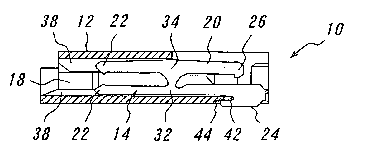
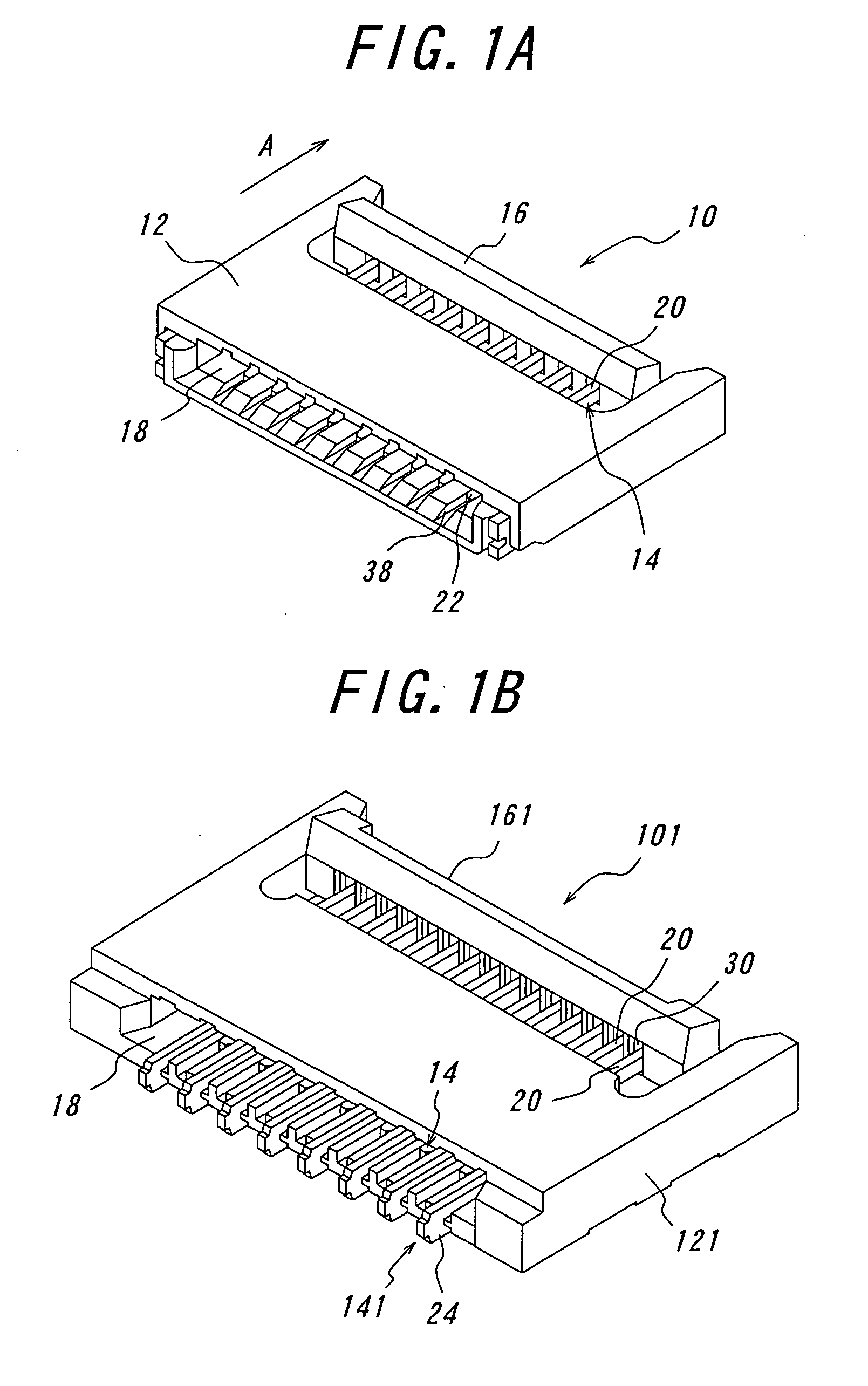
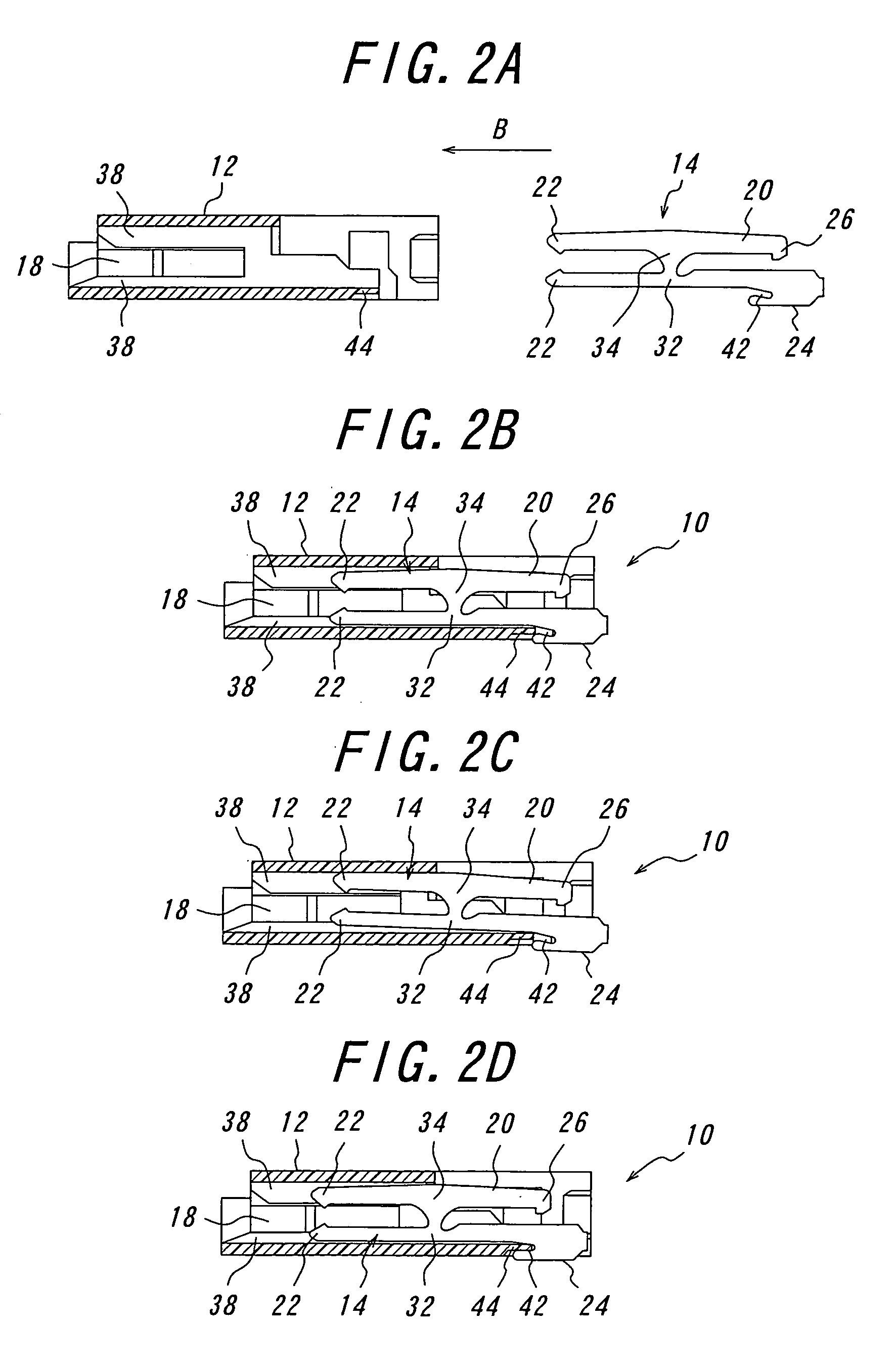
[0028] A connector 10 according to the invention will be explained with reference to the drawings. FIG. 1A is a perspective view of the connector according to the invention viewed from the side of its fitting opening, and FIG. 1B is a perspective view of the connector with contacts arranged in staggered or zigzag fashion, viewed from the fitting opening. FIGS. 2A to 2D are explanatory views for mounting contacts in its housing. FIG. 3A is a partly sectional perspective view of the connector before a flexible printed circuit board is inserted therein and FIG. 3B is a partly sectional perspective view of the connector after the flexible printed circuit board has been inserted and a slider has been pivotally moved. The connector 10 according to the invention mainly comprises the housing 12, the slider 16 and the contacts 14.

[0029] The components of the connector 10 according to the invention will be explained by referring to the drawings. First, the contacts 14 forming one important a...


PUM


Abstract

A connector to be detachably fitted with a flexible printed circuit board or a flexible flat cable includes a required number of contacts, a housing for holding and fixing therein the contacts, and a slider for pressing the circuit board or flat cable against the contacts. The housing is provided with anchoring portions at locations corresponding to connection portions of the contacts. Connection portions of the contacts are each formed with an oblique recess to engage the anchoring portion of the housing. When the contact is being inserted into an insertion groove of the housing, a contact portion of the contact comes into contact with an upper wall of the insertion groove, but on proceeding of the insertion, the contact portion of the contact will return into parallel with the insertion groove with the aid of guidance of the engagement of the oblique recess with the anchoring portion of the housing without any oblique positioning of contacts, thereby achieving stable electrical connection of the connector.

Description

BACKGROUND OF THE INVENTION [0001] The present invention relates to a connector having a mechanism for pressing contacts against a flexible printed circuit board or flexible flat cable for use in a mobile phone or cellular phone, notebook personal computer, digital camera and the like, and more particularly to a connector capable of inserting contacts in parallel with insertion grooves of its housing. [0002] Among the connectors for use in mobile phones, charge couples device (CCD) cameras and the like, connectors of one kind mainly comprise a housing and contacts, and a flexible printed circuit board is inserted into the housing to be brought into contact with contact portions of the contacts. This type of connectors is so-called “non-zero-insertion force” (NZIF) type. The connectors of the other kind mainly comprise a housing, contacts and a slider so that a flexible printed circuit board is embraced by the housing and the slider. The connectors of this type are so-called “zero-in...

Claims


Application Information

Patent Timeline
Patent Type & Authority Applications(United States)
IPC IPC(8): H01R24/00
CPCH01R12/88H01R12/771
Inventor SUZUKI, MASAYUKI
Owner DDK LTD
Why Eureka
Try Eureka