Device and method of arthroscopic knee joint resurfacing

Inactive Publication Date: 2005-06-23
CLARK RON
6 Cites 237 Cited by

AI-Extracted Technical Summary

Problems solved by technology

The sizes of incisions required to insert the implants are often relatively large.
Moreover, the pri...

Method used

[0025] The tibial implant component 22 may be attached to the tibia to prevent migration of the tibial implant component 22 with respect to the tibia, or the tibial implant component 22 may be free floating on the tibia. The tibial implant component 22 may be cemented in place using an access channel 38 passing obliquely from the anterior proximal tibia into the central aspect of the tibial plateau as illustrated in FIG. 7. The access channel 38 allows cement to be placed on the tibial implant 22 in a manner to avoid unwanted spreading of the cement. Moreover, a strand or other tensioning device may o...

Benefits of technology

[0006] A knee joint resurfacing implant including femoral and tibial implant components is disclosed. The femoral implant component includes an apex and supports on the proximal surface which are configured to share loads between cortical and cancellous bone material when the femoral implant component is implanted on the distal end of a prepared femur. The femoral implant may be attached to the femur using screws or other rigid members such as a peg, pin, or stem that traverses the external articulating surface and has a terminal surface that uniformly matches the external a...

Abstract

A knee joint resurfacing implant is disclosed. The knee joint resurfacing implant may include femoral implant and tibial implant components. The femoral implant components may be attached to the femur using screws or other fixation devices. The femoral implant component may be configured to share loads between cortical and cancellous bone material. The tibial implant components are formed in modular portions which may be assembled within the knee joint and may be free-floating or fixed to the tibial surface. The implant components are of such a size and configuration that the components may be placed into the knee joint through an external skin incisions that measure 3 cm or less. Accordingly, the size of skin incisions required for implantation may be reduced when compared to incisions which are now commonly used.

Application Domain

Technology Topic

FemurCancellous bone +8

Image

  • Device and method of arthroscopic knee joint resurfacing
  • Device and method of arthroscopic knee joint resurfacing
  • Device and method of arthroscopic knee joint resurfacing

Examples

  • Experimental program(1)

Example

[0016] For the purposes of promoting an understanding of the principles in accordance with the disclosure, reference will now be made to the embodiments illustrated in the drawings and specific language will be used to describe the same. It will nevertheless be understood that no limitation of the scope of the disclosure is thereby intended. Any alterations and further modifications of the inventive features illustrated herein, and any additional applications of the principles of the disclosure as illustrated herein, which would normally occur to one skilled in the relevant art and having possession of this disclosure, are to be considered within the scope of the disclosure claimed.
[0017] In describing and claiming the present disclosure, the following terminology will be used in accordance with the definitions set out below.
[0018] As used herein, the terms “comprising,”“including,”“containing,”“characterized by,” and grammatical equivalents thereof are inclusive or open-ended terms that do not exclude additional, unrecited elements or method steps.
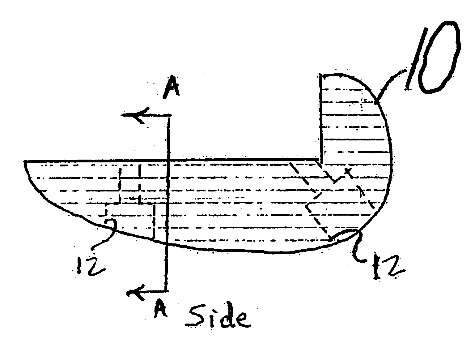
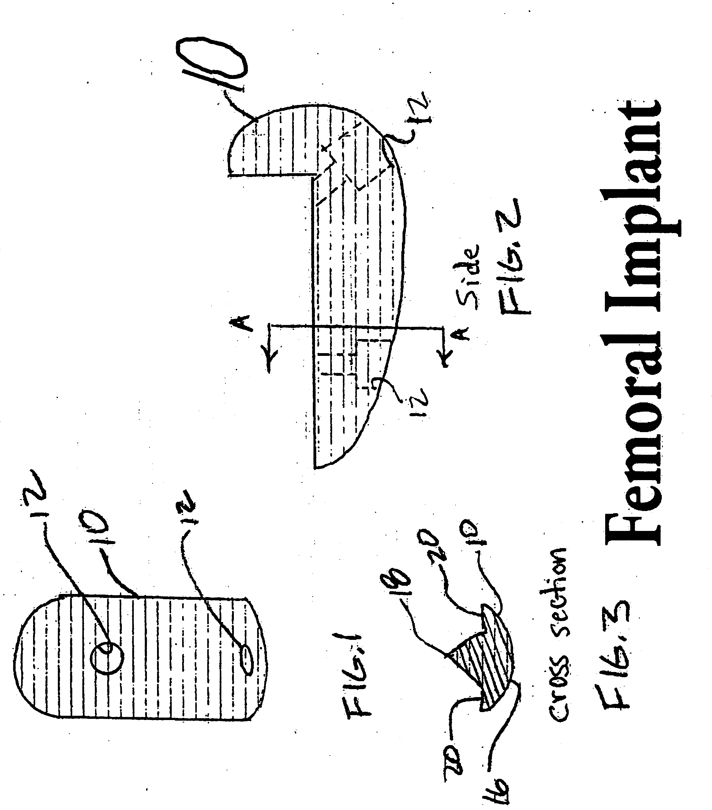
[0019] Referring now to FIG. 1, a front view of a femoral implant 10 is shown. The femoral implant 10 may have one or more screw receiving holes 12 for receiving a screw 14 for attaching the femoral implant 10 to the distal end of the femur, as shown most clearly in FIG. 7. As shown in FIG. 3, which shows a cross-sectional view of the femoral implant 10 taken along the line A-A in FIG. 2, the femoral implant 10 may include a curved surface 16 configured for contacting a tibial implant 22 as shown in FIG. 7. The femoral implant 10 may also include an apex portion 18 and supports 20 to engage the prepared distal end of the femur. The apex portion 18 may be configured to be received in the cancellous bone material of the femur, whereas the supports 20 may be configured to contact the cortical bone material of the femur, so that load sharing between the cortical bone and the cancerous bone may be accomplished.
[0020] The femoral implant 10 may be used to repair a single condyle, referred to as a unicondylar replacement. Also, two femoral implants 10 may be used in a bi-condylar replacement within the scope of the present disclosure.
[0021] The femoral component 10 may be shaped to reproduce the weight bearing articular surface of the knee. The femoral component 10 may be configured to be 15-20 mm in width, for example, with an anatomical assortment of lengths and thicknesses. It will be understood that other widths and dimensions may be used within the scope of the present disclosure. Moreover, it will be understood that the femoral implant 10 may be implanted without resurfacing the entire width of the condyle. Accordingly, the femoral implant 10 may form a narrow rim on the condyle which may cooperate with the remaining portion of the condyle. The femoral component 10 may be made of a high molecular weight polyethylene (HMWPE) or any other suitable material known to those skilled in the art.
[0022] The screw receiving holes 12 may be formed of two distinct dimensions, as shown most clearly in FIG. 2, to allow for a cancellous type of screw to pass in order to provide fixation to the femur, with or without polymethylmethacrylate (PMMA) cement.
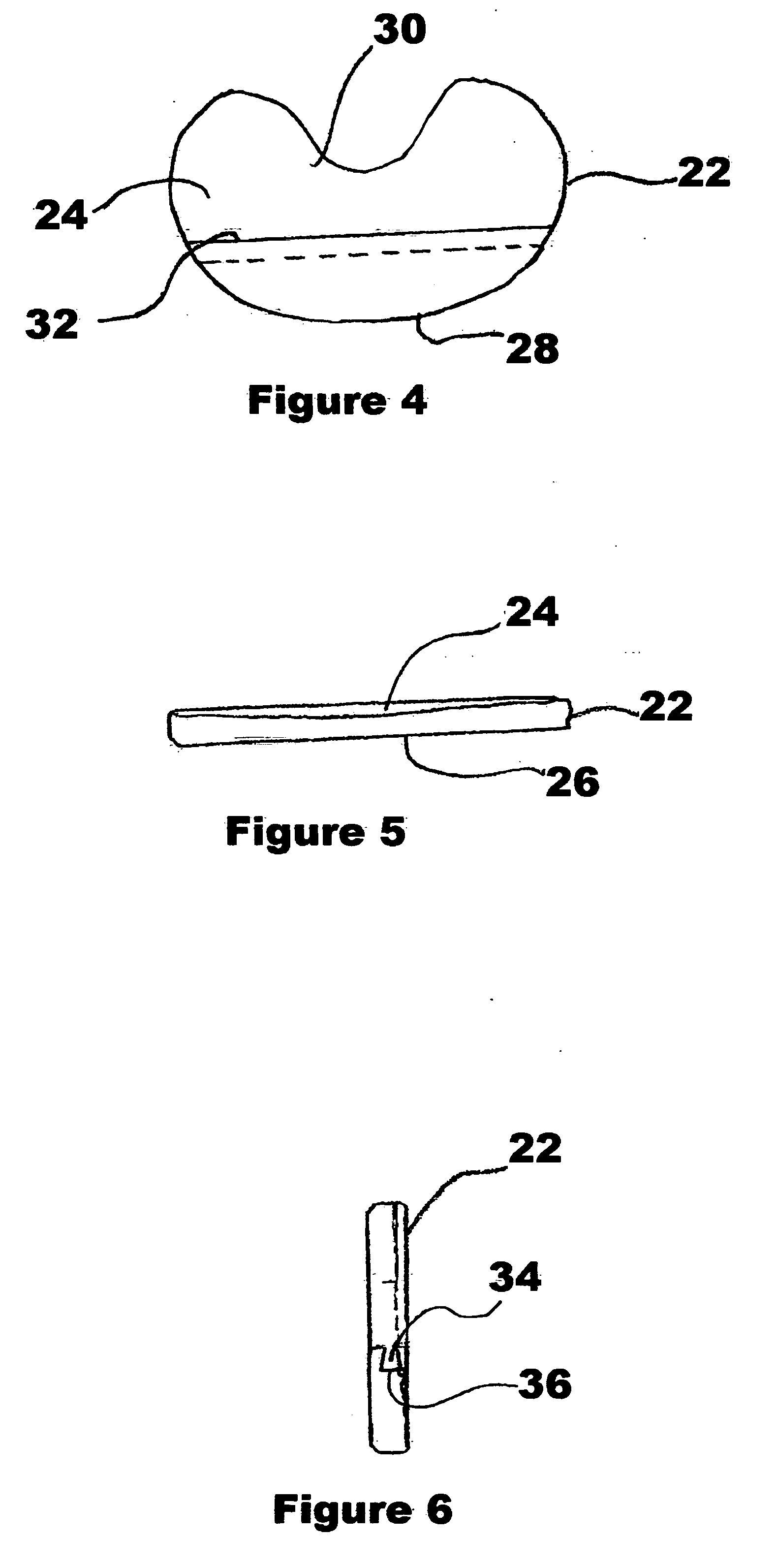
[0023] As shown in FIGS. 4-7, the tibial implant component 22 may be formed having a semicircular circumference. The tibial implant component 22 may have a concave superior surface 24 and a planar inferior surface 26. The tibial implant component 22 may be divided into a medial portion 28 and a lateral portion 30 by an implant joint 32. The implant joint 32 may allow the tibial implant component 22 to be inserted into the knee joint in separate pieces through an arthroscopic portal and then assembled within the knee joint at the time of implantation under arthroscopic visualization. It will be understood that the implant joint 32 may be in the form of a dovetailed joint with a projection 34 on the lateral portion 30 and a channel 36 on the medial portion 28, or the projection 34 may be formed on the medial portion 28 and the channel 36 may be on the lateral portion 30. It will also be appreciated that other types of junctions or interlocking geometric interfaces may be used within the scope of the present disclosure. Moreover, the implant joint 32 may be self locking and may include any of a variety of fasteners or attaching devices to prevent the medical portion 28 and the lateral portion 30 from becoming separated.
[0024] It will be understood that the tibial implant 22 may be formed of metal, polymer, or any other suitable material known to those skilled in the art.
[0025] The tibial implant component 22 may be attached to the tibia to prevent migration of the tibial implant component 22 with respect to the tibia, or the tibial implant component 22 may be free floating on the tibia. The tibial implant component 22 may be cemented in place using an access channel 38 passing obliquely from the anterior proximal tibia into the central aspect of the tibial plateau as illustrated in FIG. 7. The access channel 38 allows cement to be placed on the tibial implant 22 in a manner to avoid unwanted spreading of the cement. Moreover, a strand or other tensioning device may optionally be placed in the access channel 38 and attached to the tibial implant component 22 by any suitable means. The strand may be a suture or any other mechanism known to those skilled in the art. Similarly, any variety of cement known to those skilled in the art may be installed through the access channel 38.
[0026] As shown in FIG. 7, which shows an exploded side view of a knee, including the femur, tibia and patella, in which the femoral implant component 10 and tibial implant component 22 are implanted, the convex curved surface 16 of the femoral implant component 10 may be configured to fit in the concave superior surface 24 of the tibial implant component 22. The inferior surface 26 of the tibial implant component 22 as shown in FIG. 5 is configured to mate to the proximal surface of the tibia as shown in FIG. 7, and the superior surface 24 of the tibial implant component 22 is configured to mate and articulate with the distal convex curved surface 16 of the femoral component 10 in a conformational relationship. Thus, the size and shape of the tibial implant 22 and femoral implant 10 and their articulating surfaces may vary to conform to a desired anatomical structure. In one embodiment of the tibial implant 22, the tibial implant 22 may be thicker on the medial side 28 than on the lateral side 30.
[0027] Orientation of the mechanical axis of the knee joint, and the depth and position of cuts made to the native surface of the knee prior to implant insertion may be facilitated by the use of a surgical navigation system that may include immediate real time data acquisition and retrieval.
[0028] The present disclosure provides surgeons and patients with a reliable and technical method and implants to appropriately resurface the worn articular surface of a single knee compartment. The design of the instruments and implants may allow skin incisions to be less than 25 mm in length. The procedure may be performed arthroscopically with surgical navigational assist.
[0029] In the foregoing, various features of the present disclosure are grouped together in a single embodiment for the purpose of streamlining the disclosure. This method of disclosure is not to be interpreted as reflecting an intention that the claimed disclosure requires more features than are expressly recited in each claim. Rather, as the claims will reflect, inventive aspects lie in less than all features of a single foregoing disclosed embodiment.
[0030] It is to be understood that the above-described arrangements are only illustrative of the application of the principles of the present disclosure. Numerous modifications and alternative arrangements may be devised by those skilled in the art without departing from the spirit and scope of the present disclosure and the appended claims are intended to cover such modifications and arrangements. Thus, while the present disclosure has been shown in the drawings and described above with particularity and detail, it will be apparent to those of ordinary skill in the art that numerous modifications, including, but not limited to, variations in size, materials, shape, form, function and manner of operation, assembly and use may be made without departing from the principles and concepts set forth herein.

PUM

no PUM

Description & Claims & Application Information

We can also present the details of the Description, Claims and Application information to help users get a comprehensive understanding of the technical details of the patent, such as background art, summary of invention, brief description of drawings, description of embodiments, and other original content. On the other hand, users can also determine the specific scope of protection of the technology through the list of claims; as well as understand the changes in the life cycle of the technology with the presentation of the patent timeline. Login to view more.

Similar technology patents

Imaging lens and imaging apparatus

ActiveUS20110080655A1Reduce in sizeWide viewingLensConditional expressionImaging lens
Owner:NANCHANG O FILM OPTICAL ELECTRONICS TECH CO LTD

Classification and recommendation of technical efficacy words

Why Eureka
Try Eureka