Surface light emitting device

a technology of surface light and emission device, which is applied in the direction of fixed installation, lighting and heating apparatus, instruments, etc., can solve the problems of increasing the cost of the panel, and not only driving up the cos

Inactive Publication Date: 2005-06-30
BOX
View PDF7 Cites 78 Cited by
  • Summary
  • Abstract
  • Description
  • Claims
  • Application Information

AI Technical Summary

Benefits of technology

[0007] It is therefore an object of the present invention to provide an inexpensive compact surface em

Problems solved by technology

In the case of the edge light type, an expensive light guiding panel is used.
Accordingly, the larger the area, the more expensive the panel.
This not only drives up costs, but also makes a device larger because the light source must be provided on the side.
Accordingly, an unevenness is caused in the brig

Method used


Image

  • Surface light emitting device
  • Surface light emitting device
  • Surface light emitting device

Examples


first embodiment

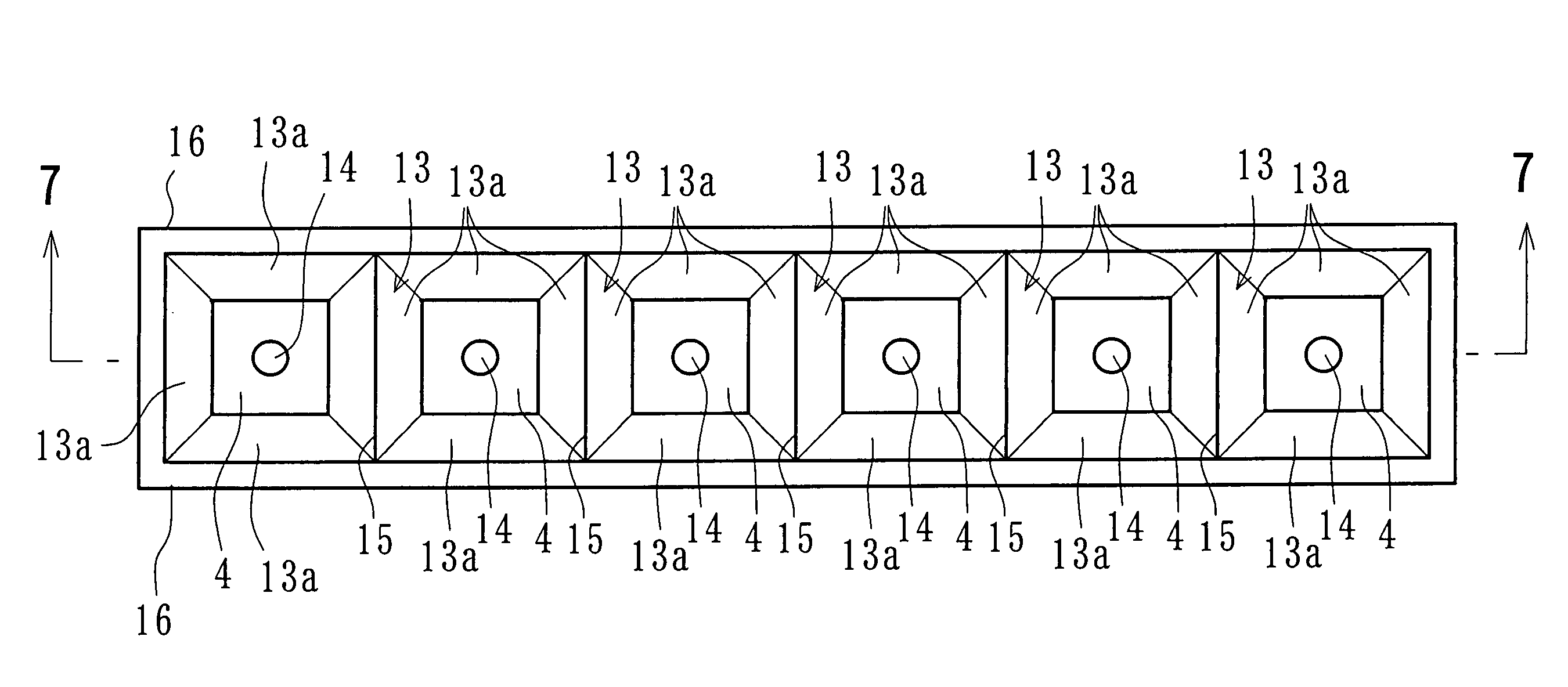
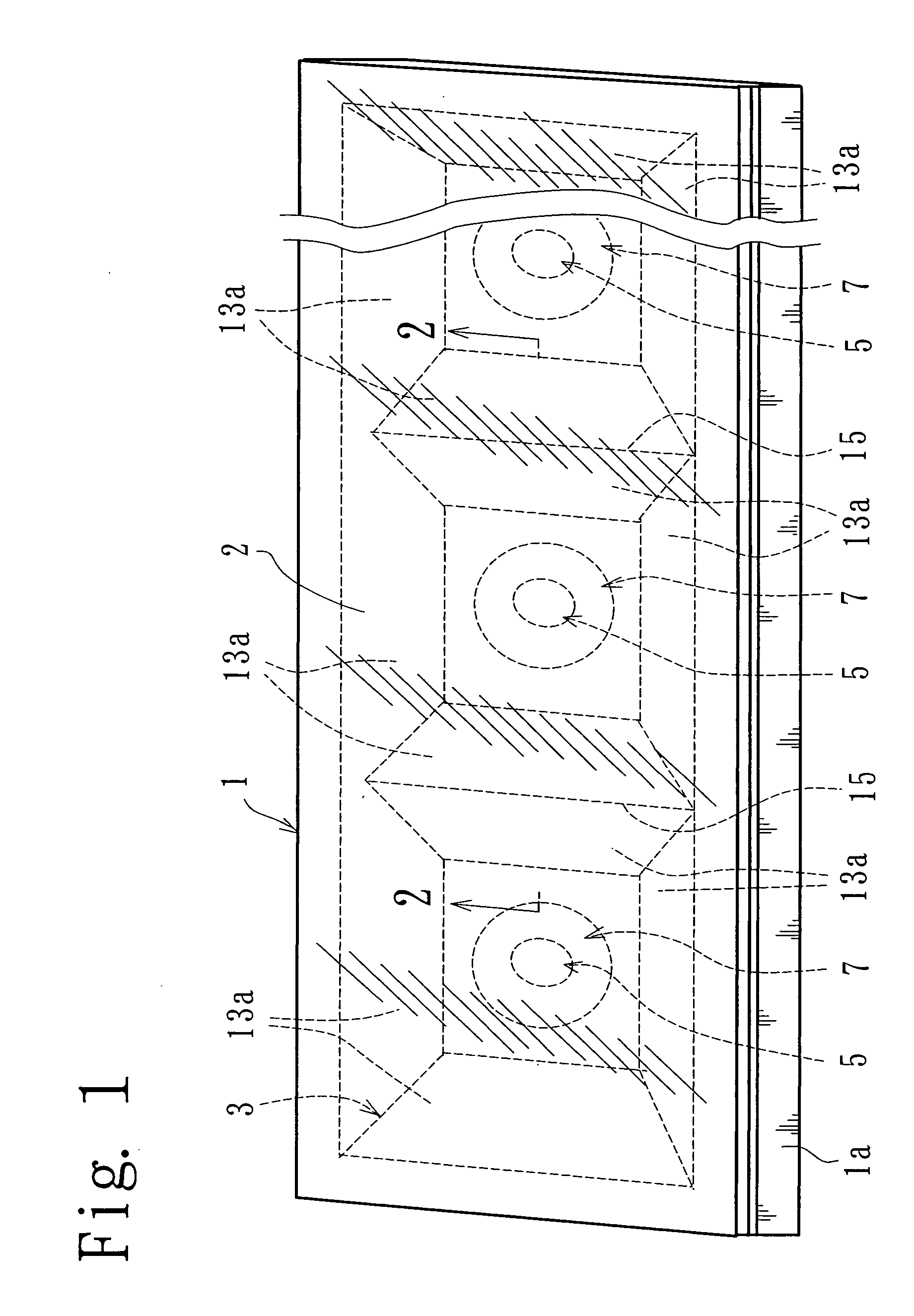
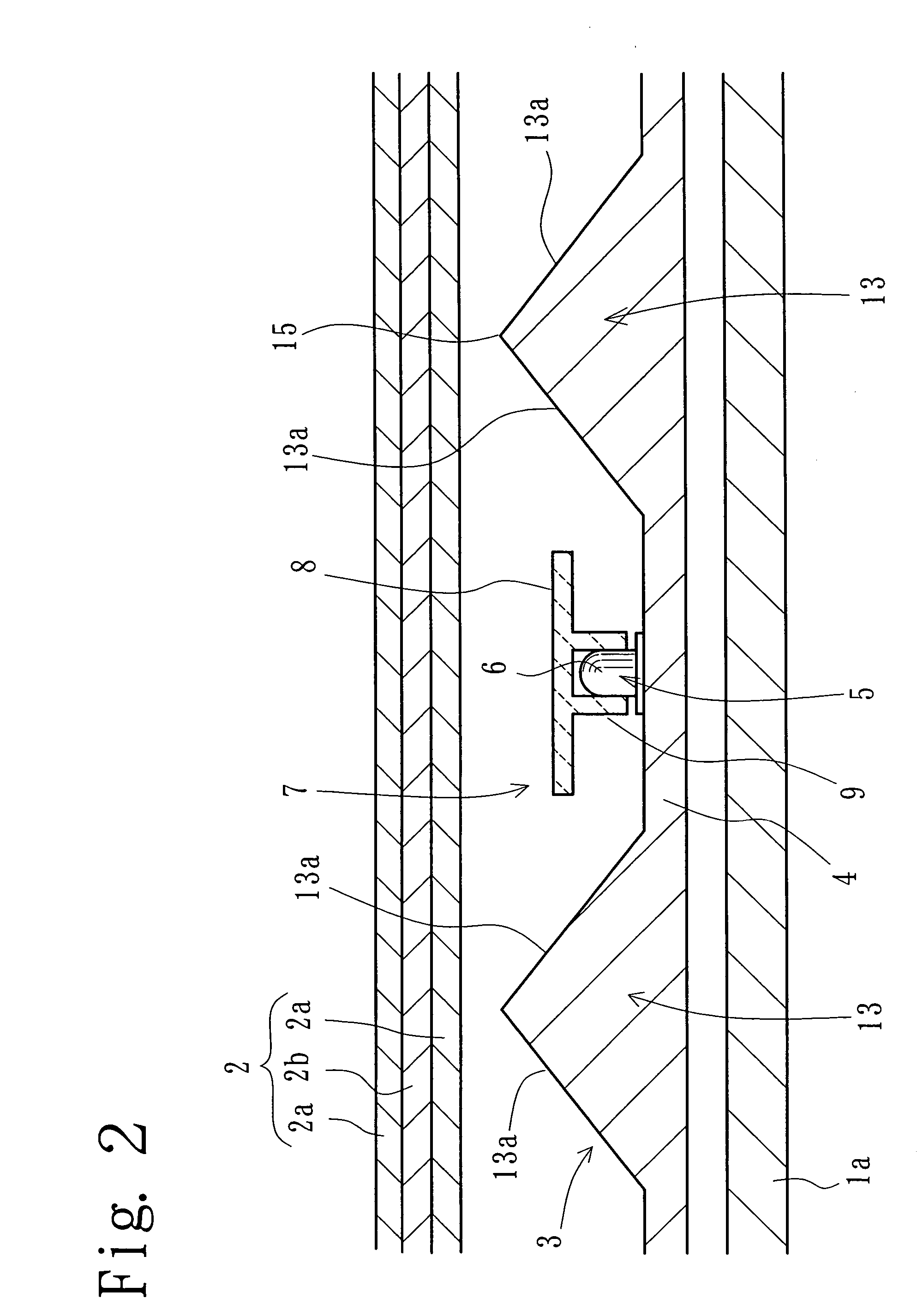
[0036] One embodiment of the present invention will now be described with reference to the accompanying drawings. FIGS. 1 through 7 relate to a first embodiment, wherein FIG. 1 is a perspective view of a surface emission (light emitting) device and FIG. 2 is a partially exploded cross-sectional view taken along the line 2-2 of FIG. 1. FIG. 3 is a view showing the installation of a light control means, FIG. 4 is a view showing the light control means from various angles, and FIG. 5 is a view showing the operation of the light control means. FIG. 6 is a view showing a reflector from a diffusion panel side and FIG. 7 is a cross-sectional view taken along the line 7-7 of FIG. 6. In the present invention, the light advancing along an optical axis of LED is referred to as the front.

[0037] In FIG. 1, a surface emission (light emitting) device, 1 is provided with a casing 1a formed in a rectangular parallelepiped to be used as an electric light guiding means and the like and a diffusion pan...

second embodiment

[0062]FIG. 8 is a second embodiment in which the surface emission (light emitting) device 1 of a minimum structure formed only by one unit is shown. In this example, each of the casing 1a, the diffusion panel 2, and the reflector 3 forms a square. The reflector 3 corresponds to that formed as only one unit in FIGS. 6, 7. If the required number of units is freely lined up and integrated in every direction according to need, a surface emission device of a given size is obtained. It is to be noted that the casing 1a and the diffusion panel 2 can be a single one having a predetermined shape and dimension for exclusive use.

third embodiment

[0063]FIGS. 9 through 12 show a third embodiment in which the light control means 7 is superposed on the reflector 3. FIG. 9 is an exploded view of a substantial part. FIG. 10 is a view showing part of the light control means from the front side, FIG. 11 is a cross-sectional view showing the installation condition thereof, and FIG. 12 shows a condition of the light control means in one unit structure.

[0064] As shown in FIGS. 9 and 10, the light control means 7 corresponds to the reflector 3 which is integrated with a number of units, each formed in a square, constructed in the same manner as those shown in FIG. 6. The light control means 7 is formed here as a single body to be directly covered on the reflector 3.

[0065] Namely, the light control means 7 is provided with a slope 23 and a ridgeline 25 corresponding to the slope section 13 and the ridgeline 15. The light control means 7 is further provided with an enlarged square bottom section 24 of a similar figure to cover the upper...


PUM


Abstract

A reflector 3 having a bottom section 4 and a slope section 13 surrounding the periphery of the bottom section 4 is provided, and an LED 5 is mounted on the center of the bottom section 4. A holder section 9 of a light control means 7 is detachably mounted to cover a lens 6 of the LED 5, while a circular plate section 18 of the light control means 7 is provided with a main reflecting section 11 and a reflecting transmission section 12. The main reflecting section 11 is designed to reduce the transmission amount from the LED 5, thereby causing most of the light to reflect on the reflector 3 side. On the other hand, the reflecting transmission section 12 permits a larger amount of transmission than in the main reflecting section 11. In this manner, it is possible to realize substantially uniform brightness in the entire upper section of the reflector 3 by the light transmitted through the main reflecting section 11 and the reflecting transmission section 12 and the light diffusely reflected from the reflector 3.

Description

BACKGROUND OF THE INVENTION [0001] 1. Field of the Invention [0002] The present invention relates to a surface emission device used in an decorative illumination sign board, an electric light display device and the like, and more particularly, to a surface emission device which permits a surface-shaped light emission using a subjacent LED provided directly below a diffusion panel. A subjacent type means here the positional relationship in which the light source is situated below the diffusion panel in the case where the diffusion panel and the light source are vertically arranged. When the diffusion panel is set up and an observer takes his position in front of the diffusion panel, this means the positional relationship in which the light source is situated at the back of the diffusion panel. The direction in which the light from the light source advances along the optical axis is hereinafter referred to as the front. [0003] 2. Description of the Prior Art [0004] Known as a surface ...

Claims


Application Information

Patent Timeline
IPC IPC(8): G02B5/08F21S2/00F21S8/04F21V7/00F21V7/10F21V13/04F21V17/04F21Y101/02G09F13/14H01L33/58H01L33/60
CPCF21V7/0016F21V7/10F21V13/04G09F13/14F21Y2101/02F21Y2105/00G02F1/133603F21V17/04F21Y2103/10F21Y2105/16F21Y2115/10
Inventor YAMAUCHI, TOSHIO
Owner BOX
Why Eureka
Try Eureka