
Constant temperature refrigeration system for extensive temperature range application and control method thereof

Active Publication Date: 2005-06-30
IND TECH RES INST
View PDF13 Cites 12 Cited by
  • Summary
  • Abstract
  • Description
  • Claims
  • Application Information

AI Technical Summary

Benefits of technology

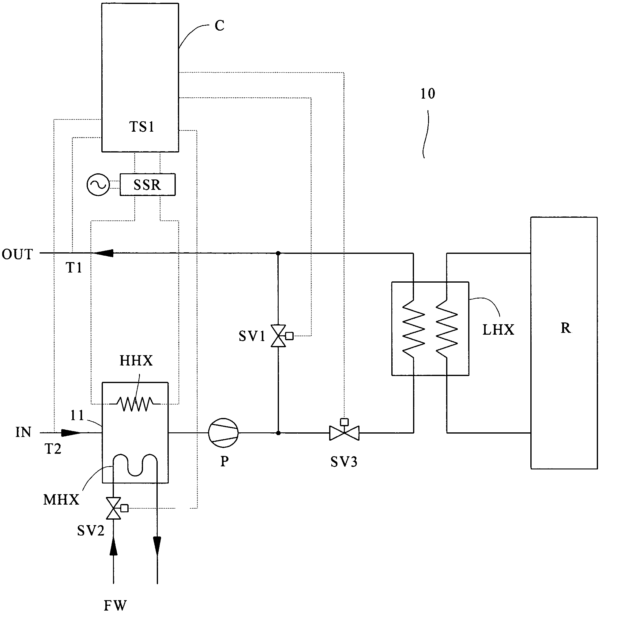
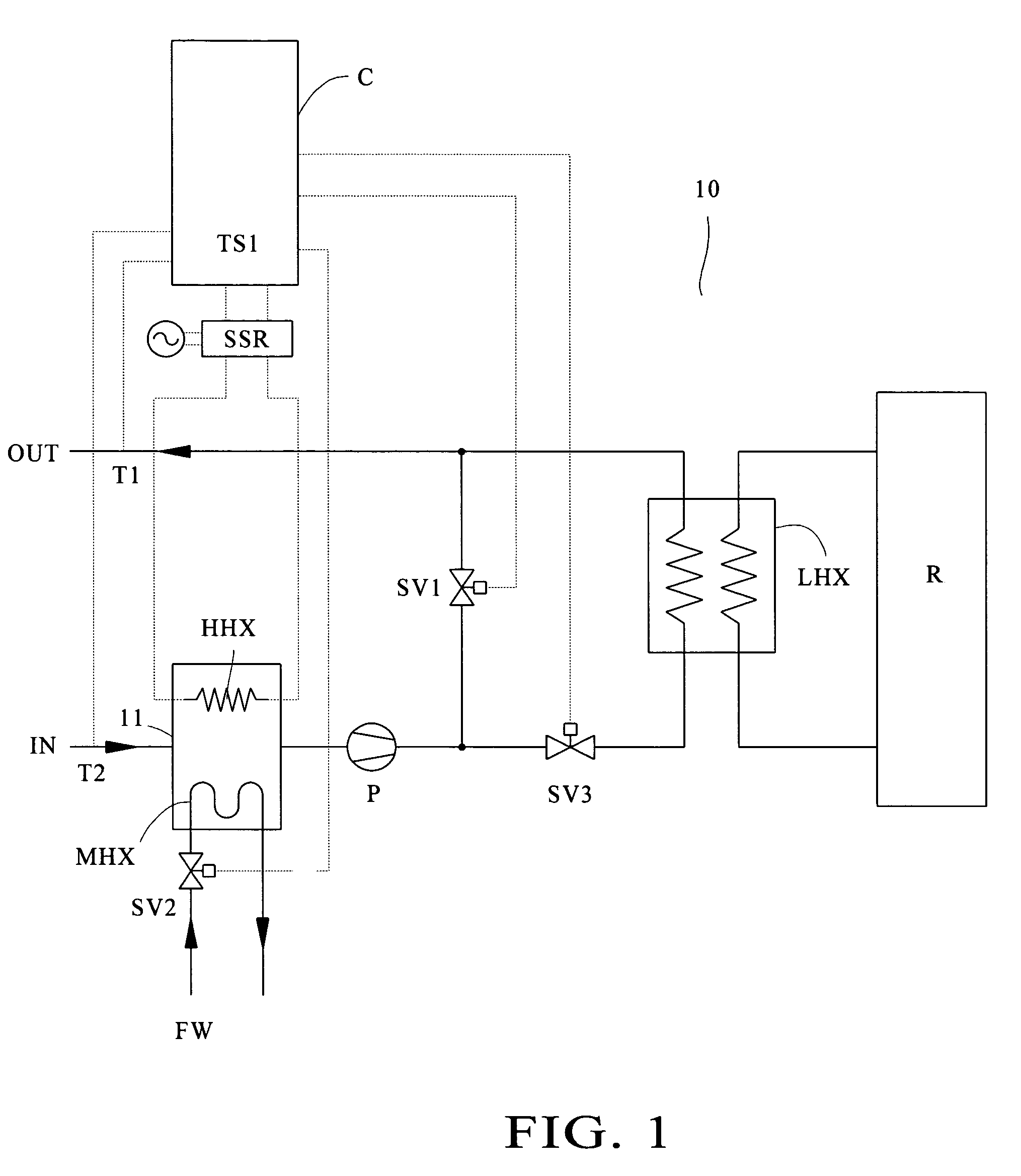
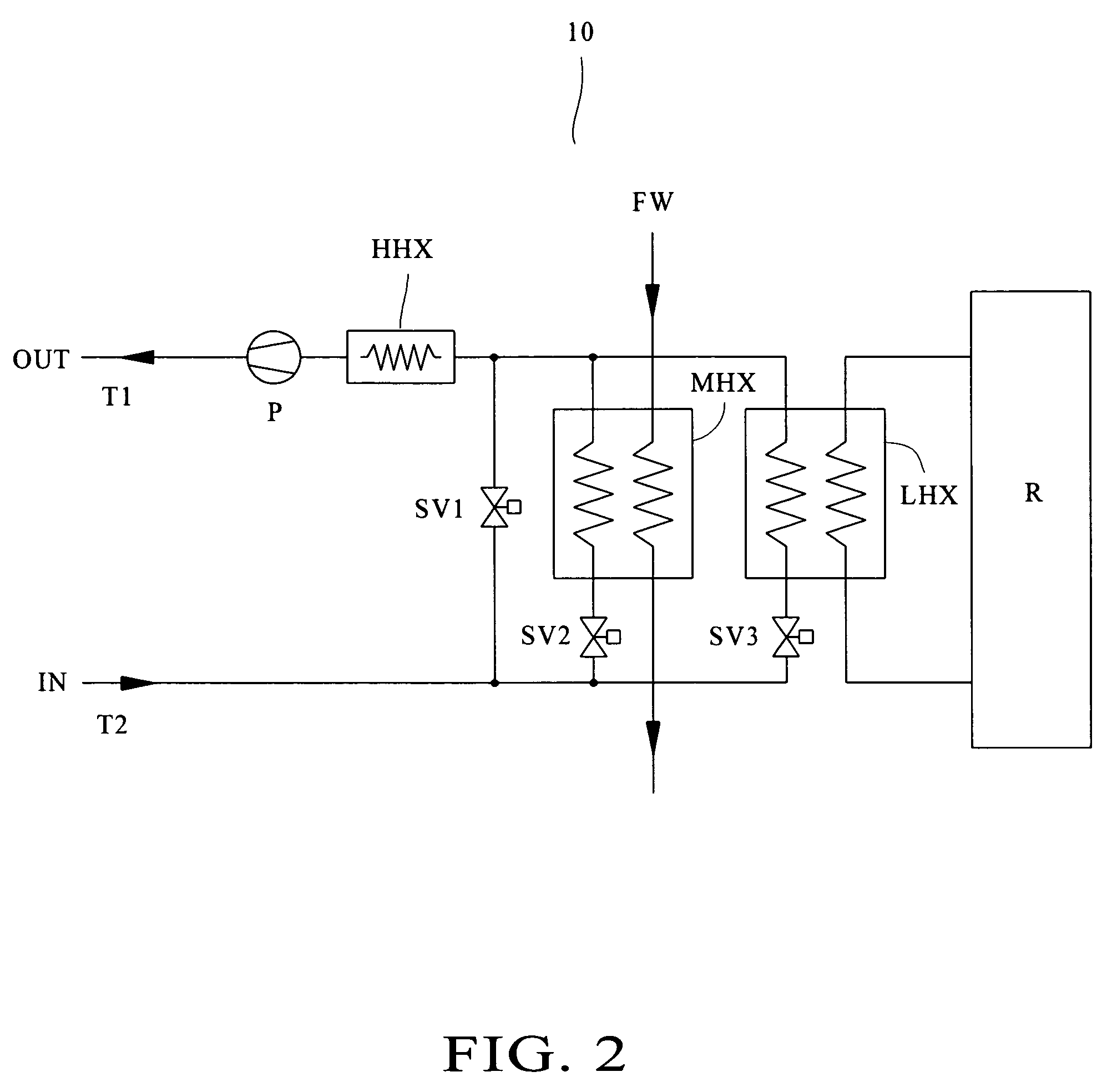
[0031] The primary object of the present invention is to provide a constant temperature refrigeration system for extensive temperature range application, which applies the facility water usually prepared in general semiconductor processes, biochemical material, food-processing and original material industries, and the refrigeration system thereof such as liquid chillers and cooling towers, in accordance with conduits and certain solenoid valves, so that as different solenoid valves are switched ON or OFF according to different temperature requirement, so as to acquire the working fluid having the exactly and precisely predetermined low temperature (−40° C. to 25° C.), medium temperature (25° C. to 50° C.) or high temperature (50° C. to 100° C.) required during various industrial manufacturing processes, a design that provides users with the energy-saving function and system maintenance for normal operations.
[0047] Preferably, a refrigerator is utilized for providing a cooling source with temperature lower than 25° C. during low-temperature application, such that heat energy generated during the manufacturing process may be brought away under the low-temperature environment for the energy-saving purpose.
[0049] Preferably, a high-temperature heat exchanger is utilized during high-temperature application, the high-temperature heat exchanger being constantly under the “ON” state after the refrigeration system is actuated, and the power regulator is utilized for fine-tuning the temperature with reference to the temperature differences from the temperature sensor, so as to achieve accurate constant temperature control.

Problems solved by technology

However, for applications under larger heat load for longer periods of time, the design of placing the cooling source and the heating source in the identical tank may easily cause abnormal actuation for high-temperature model compressors.
were low-temperature refrigeration systems utilized for maintaining the high-temperature cooling function, electricity shall be wasted, along with tremendous strain on the life time for the compressors because of the huge temperature differences; especially for apparatus in manufacturing processes required to run non-stop 24-hours per day for long periods of time, the energy put into such manufacturing processes shall surely be excessively wasted. Fo
Yet, if the heat load of the working fluid becomes too high, the medium-temperature heat exchanger MHX then might fail to lower the temperature, which means when the heat load of the working fluid is greater than the heat exchanging capacity of the medium-temperature heat exchanger MHX, the temperature of the working fluid would be higher and higher without being able to be controlled under constant temperature.
et since the 25° C. facility water is still kept in the medium-temperature heat exchanger MHX, as the control temperature is near the low temperature, the temperature of the facility water in the medium heat exchanger MHX would be lower and lower because of the heat conduction to the point where the control temperature is near −40° C., such that the temperature of the facility water in the medium heat exchanger MHX would be lower than 0° C., thus causing the facility water to be frozen so as to cause the medium-temperature heat exchanger MHX to cracks and damages.

Method used


Image

  • Constant temperature refrigeration system for extensive temperature range application and control method thereof
  • Constant temperature refrigeration system for extensive temperature range application and control method thereof
  • Constant temperature refrigeration system for extensive temperature range application and control method thereof

Examples


first embodiment

[0074]FIG. 8 shows a plot plan of a constant temperature refrigeration system 10 for extensive temperature range application controlled by the present controlling method according to the present invention, which is similar to the second example shown in FIG. 2, comprising a refrigerator R, a low-temperature heat exchanger LHX, a medium-temperature heat exchanger MHX, a high-temperature heat exchanger LHX, a pump P, a first solenoid valve SV1, a second solenoid valve SV2 and a third solenoid valve SV3, heaters HT1 and HT2, and temperature switches TR1 and TR2. The power regulator, the temperature sensor and the controller are all omitted in FIG. 8 for the means of electrical connections thereof are all identical to those in FIG. 1.

[0075] As shown in FIG. 8, the high-temperature heat exchanger HHX and the pump P are both mounted at the output end, with the conduit thereof being connected in tandem thereon with the first solenoid valve SV1, whereas the second solenoid valve SV2 is conn...

second embodiment

[0082] Please continue refer to the second embodiment in FIG. 11, which is similar to the third example shown in FIG. 3, and since the heaters HT1 and HT2 and the temperature switches TR1 and TR2 function identically to those in the first example of FIG. 1, they are not to be repeated herein.

[0083] As for the controlling methods for constant temperature shown respectively in FIG. 8 and FIG. 11, which are the heating and cooling models and procedures thereof, since they are identical to those in the examples shown in FIG. 2 and FIG. 3, they are not to be repeated herein.

[0084] Please refer to the third embodiment in FIG. 12, wherein a three-way solenoid valve 4 and the connecting conduits thereof are used for replacing the conventional first and third solenoid valves SV1 and SV3 and related conduits in FIG. 1. Please continue refer to the fourth embodiment in FIG. 13, wherein the three-way solenoid valves SV4 and SV5 and the connecting conduits thereof are used for replacing the con...


PUM


Abstract

A constant temperature refrigeration system for extensive temperature range application comprising a refrigerator, a low-temperature heat exchanger, a medium-temperature heat exchanger, a high-temperature heat exchanger, a pump, a first solenoid valve, a second solenoid valve, a third solenoid valve, a temperature sensor, a power regulator, a controller and a plurality of heaters, the temperature sensor is utilized for determining the working fluid temperature and compare the actual input temperature, the actual output temperature and the predetermined temperature, and the controller is utilized for switching the first solenoid valve, the second solenoid valve and the third solenoid valve for conveying the fluid to flow through various heat exchangers so that the working fluid is heated or cooled, with the result being that the working fluid temperature outputted is to reach the predetermined temperature, so as to acquire the working fluid having the exactly and precisely predetermined low temperature (−40° C. to 25° C.), medium temperature (25° C. to 50° C.) or high temperature (50° C. to 100° C).

Description

BACKGROUND OF THE INVENTION [0001] 1. Field of the Invention [0002] The present invention relates to a constant temperature refrigeration system for extensive temperature range application and a control method thereof, more particularly, to a refrigeration system and a method for controlling such refrigeration system; such refrigeration system is for keeping working fluids under constant temperature, and such working fluids are utilized for manufacturing processes in semiconductor, biochemical material, food-processing and original material industries. [0003] 2. Description Of Related Arts [0004] Refrigeration equipment required by general manufacturing processes usually adopts a coolant compression refrigerator in cooperation with an electrical heating device for automatic compensation, thus achieving the dual functions of heating and cooling, and accurately maintaining the predetermined temperature of working fluids such as coolants, non-freezing liquids, brine or liquid mixtures ...

Claims


Application Information

Patent Timeline
IPC IPC(8): F25B1/00F25B41/00F25B49/00F25D17/02
CPCF25D17/02
Inventor HUANG, EH-DIHCHANG, WEN-RUEY
Owner IND TECH RES INST
Learn More