Rotational angle detecting apparatus and torque detecting apparatus

a detection apparatus and rotational angle technology, applied in the direction of electrical/magnetically converting sensor output, instruments, transportation and packaging, etc., can solve the problems of hardly getting the rotational angle precisely, the error included in the calculation result becomes larger than the original error

Inactive Publication Date: 2005-06-30
JTEKT CORP
View PDF7 Cites 3 Cited by
  • Summary
  • Abstract
  • Description
  • Claims
  • Application Information

AI Technical Summary

Benefits of technology

[0006] The present invention has been proposed in view of the above-described problem, and an object thereof is to provide a rotational angle detecting apparatus capable of precisely obtaining rotational angle.
[0007] Another object of the present invention is to provide a torque detecting apparatus capable of precisely detecting torque value.
[0009] According to the rotational angle detecting apparatus of the present invention, since such a calculation that a large error is resulted in is not carried out, a rotational angle detecting apparatus capable of precisely obtaining rotational angle can be achieved.
[0011] According to the torque detecting apparatus of the present invention, since such a calculation that a large error is resulted in is not carried out, a torque detecting apparatus capable of precisely obtaining torque value can be achieved.

Problems solved by technology

However, the detection signals include some errors such as ripples.
When the calculation such as sin θ / cos θ is executed using the detection signals including the errors, the errors included in the result of the calculation become larger than the original errors.
Therefore, there resides such a problem that rotational angle is hardly obtained precisely.

Method used


Image

  • Rotational angle detecting apparatus and torque detecting apparatus
  • Rotational angle detecting apparatus and torque detecting apparatus
  • Rotational angle detecting apparatus and torque detecting apparatus

Examples


Embodiment Construction

[0025] Hereinafter, referring to the drawings showing the embodiments, the present invention will be described in detail.

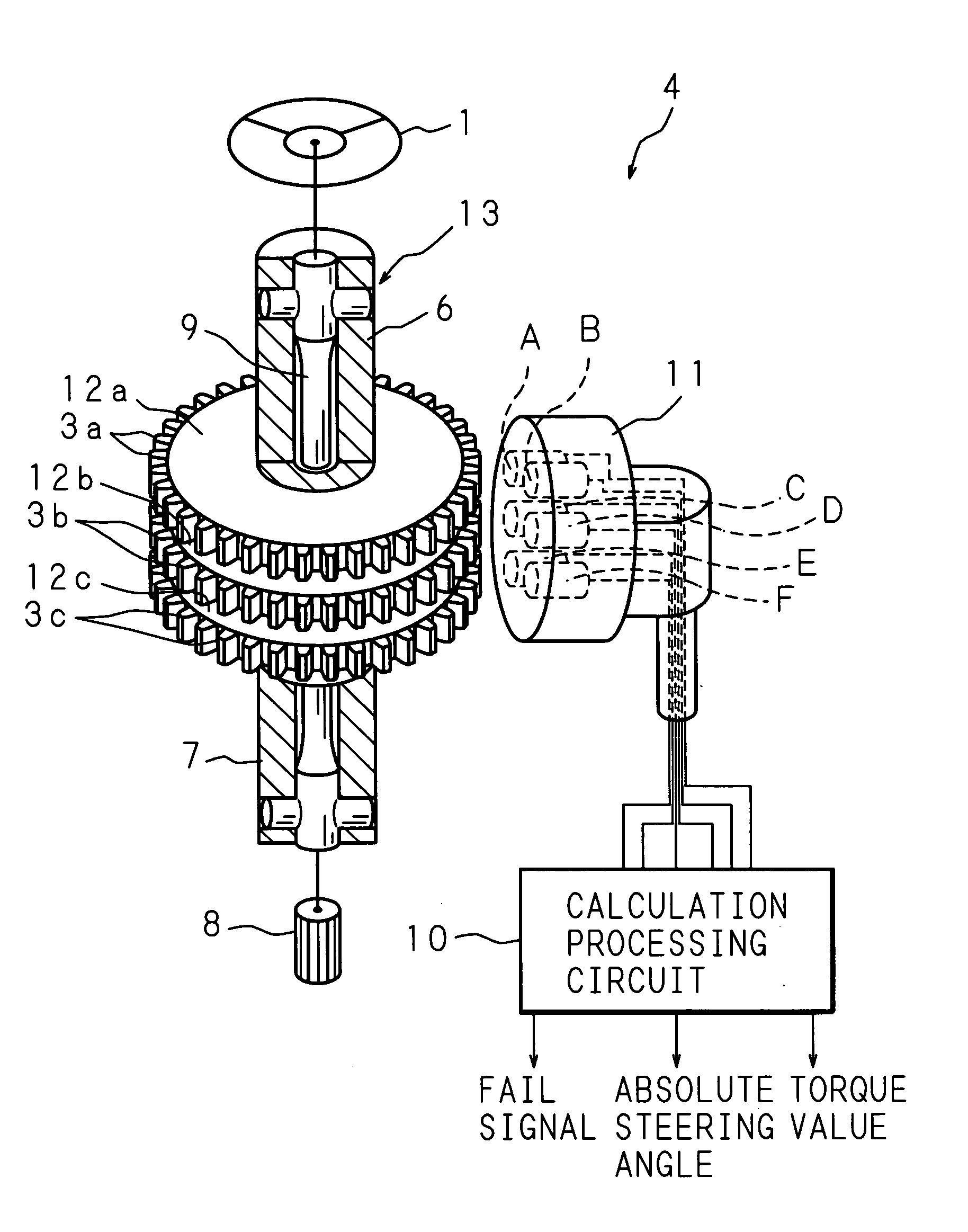
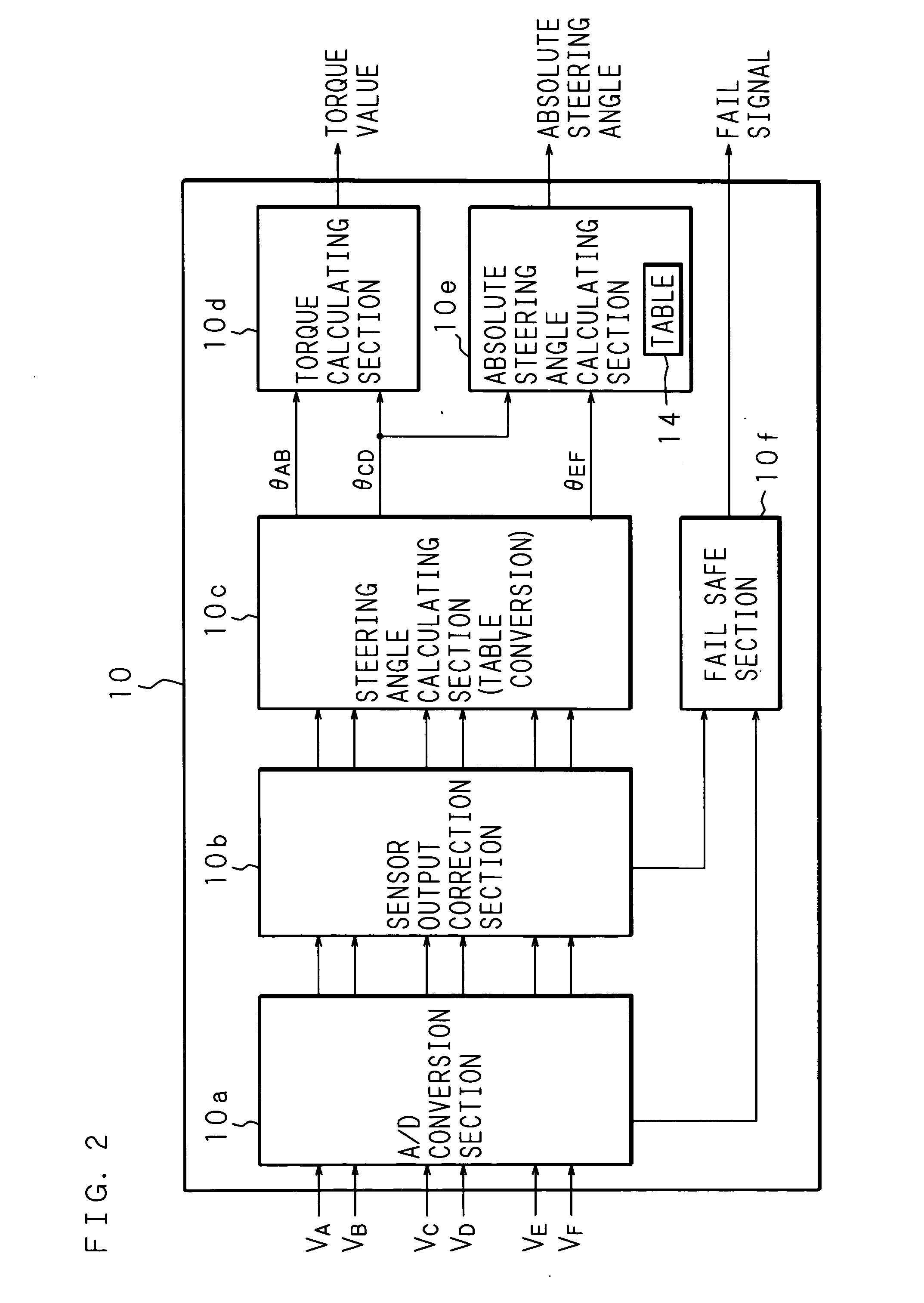
[0026]FIG. 1 is a view schematically showing the constitution of a rotational angle detecting apparatus and a torque detecting apparatus according to an embodiment of the present invention. The rotational angle detecting apparatus and the torque sensor 4 (torque detecting apparatus) comprise an input shaft 6 (rotor, first shaft) of which upper end is joined to a steering member 1 (steering wheel) and an output shaft 7 (rotor, second shaft) of which lower end is joined to a pinion 8 of a steering mechanism. The input shaft 6 and the output shaft 7 are coaxially joined to each other being interposed by a torsion bar 9 (connection shaft) of a small diameter. Thus, a steering shaft 13, which connects the steering member 1 to the steering mechanism, is structured. The vicinity of the connecting section between the input shaft 6 and the output shaft 7 is structured as ...


PUM

PropertyMeasurementUnit
rotational angleaaaaaaaaaa
electrical angleaaaaaaaaaa

Abstract

A rotational angle detecting apparatus, in which first targets and second targets, the number thereof is coprime with each other, are provided at the rotors rotating coaxially with each other. Rotational angle of the rotor is detected based on the detection signals from each of two sensors disposed opposite to the targets respectively, which output detection signals having phases different from each other as the rotor rotates. Based on a magnitude relation between one detection signal and the other detection signal from each of the two sensors, the range of the electrical angle of the other detection signals is determined. Relation between a detection signal and an electrical angle is stored in advance. Based on the determined electrical angle, and referring to the relation, the electrical angle of the other detection signal is obtained; thus, the rotational angle of the rotor is detected.

Description

CROSS-REFERENCE TO RELATED APPLICATIONS [0001] This Nonprovisional application claims priority under 35 U.S.C.§119(a) on Patent Application No. 2003-435522 filed in Japan on Dec. 26, 2003, the entire contents of which are hereby incorporated by reference. BACKGROUND OF THE INVENTION [0002] The present invention relates to a rotational angle detecting apparatus and a torque detecting apparatus comprising one or a plurality of targets provided at a rotor and a plurality of detection means disposed opposite to the targets, for outputting detection signals having phases different from each other in accordance with each position of the targets as the rotor rotates. [0003] As a steering apparatus for automobiles, an electric power steering apparatus, which drives an electric motor to assist steering and reduce driver's load, is known. Such electric power steering apparatus comprises an input shaft joined to steering member (steering wheel), an output shaft joined to steerable wheels via a...

Claims


Application Information

Patent Timeline
Patent Type & Authority Applications(United States)
IPC IPC(8): B62D6/10B62D15/02G01B7/00G01B7/30G01D5/16G01D5/244G01L3/10
CPCB62D6/10B62D15/0215G01D5/24409G01L3/104G01D5/2449G01L3/109G01D5/24457
Inventor TOKUMOTO, YOSHITOMO
Owner JTEKT CORP
Why Eureka
Try Eureka