
Track guided vehicle system

Active Publication Date: 2005-06-30
MURATA MASCH LTD
View PDF6 Cites 18 Cited by
  • Summary
  • Abstract
  • Description
  • Claims
  • Application Information

AI Technical Summary

Benefits of technology

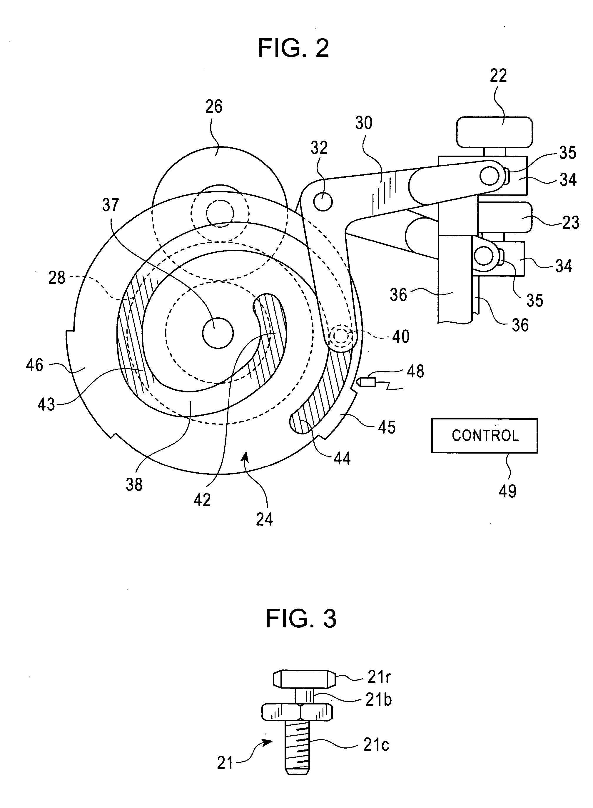
[0010] According to the aspect of the present invention in claim 2, when the cam plate is rotatively moved, the cam follower, for example, reciprocates in accordance with the spiral cam. This elevates or lowers the corresponding branching roller. The spiral cam is provided with the areas having the almost fixed radii of curvature from the center of rotative movement of the cam plate. When the cam follower lies in one of these areas, the cam plate is stopped. Then, the height position of the branching roller measured when its elevation or lowering is stopped is almost fixed in spite of a small variation in the stopped position of the cam plate. Therefore, the height position of the branching roller can be precisely controlled.
[0011] According to the aspect of the present invention in claim 3, branching or rectilinear progression is selected by elevating or lowering the branching rollers in the area in the rectilinear progression section in which a gap is created between each branching roller and the corresponding guide track. Thus, the elevation and lowering of the branching rollers does not interfere with the guide tracks. This eliminates the need to decelerate the track guided vehicle in front of the branching portion. Consequently, the branching rollers can be smoothly elevated and lowered. Further, in the branching portion, the track guided vehicle is supported by pressing the right or left branching rollers and right or left guide rollers against the outer and inner surfaces of the corresponding guide track so as to create substantially no gaps. Accordingly, even where running wheels are separated from a floor or ground surface, the track guided vehicle is not shaken or impacted. Therefore, the track guided vehicle can run at high speed regardless of whether it runs straight through or shifts to a branch line in the branching portion.

Problems solved by technology

Consequently, the running track has a complicated shape.

Method used


Image

  • Track guided vehicle system
  • Track guided vehicle system
  • Track guided vehicle system

Examples


Embodiment Construction

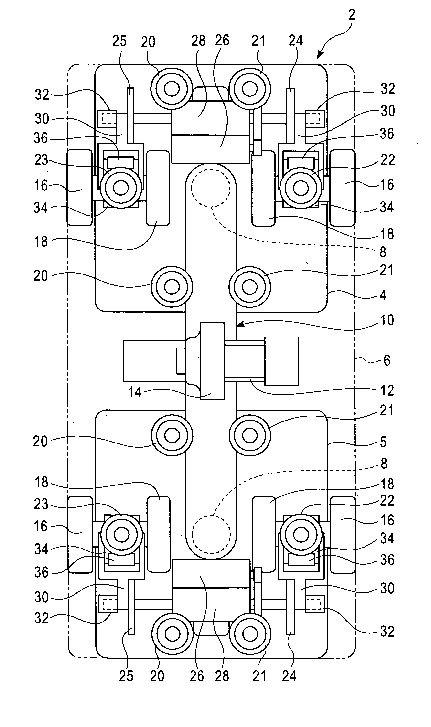
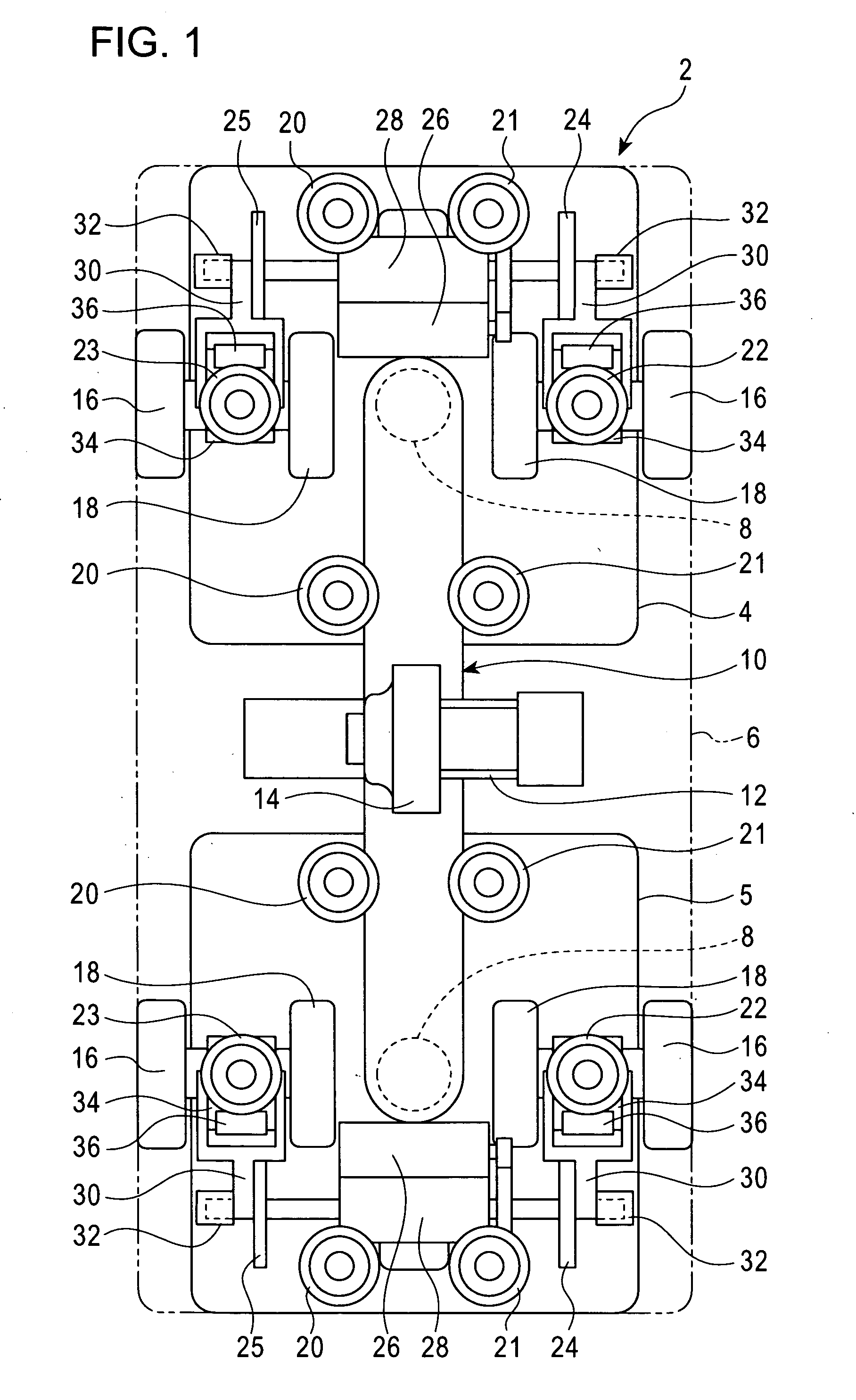
[0025] In the figures, 2 is an overhead traveling vehicle, and 4, 5 are front and rear paired bogies. 6 is an overhead traveling vehicle main body. The overhead traveling vehicle main body 6 is supported at the bottom of the bogies 4, 5 using a front and rear shafts 8, 8. A frame 10 is provided so as to connect the front and rear shafts 8, 8 together. A drive wheel 14 is driven via a running motor 12 on the frame 10. The drive wheel 14 is pressed by urging means (not shown in the drawing) against a bottom surface of an upper part of a running track to allow the overhead traveling vehicle 2 to run.

[0026] Each of the front and rear bogies 4, 5 is provided with free running wheels 16, 18 and runs using a top surface of a lower part of the running track as a tread. A total of four guide rollers 20, 21 including the front and rear guide rollers, and the right and left guide rollers are provided at the top of each of the bogies 4, 5, and the guide rollers 20, 21 are guided using inner gu...


PUM


Abstract

Guide tracks 56, 56 projecting in a vertical direction are provided in a right and left of a running track 50 and left and right guide rollers 20, 21 are provided on a track guided vehicle and guided using inner surfaces of the left and right guide tracks. Branching rollers 22, 23 each comprising elevating and lowering means are provided in the right and left of the track guided vehicle and outside the right and left guide tracks. Thus, branching and rectilinear progression of the track guided vehicle is controlled by switching between a state where the branching rollers 22, 23 are elevated or lowered to guide the track guided vehicle using outer surfaces of the guide tracks 56, 56 and a state where the branching rollers 22, 23 do not contact with the outer surfaces. Whether the track guided vehicle runs straight or shifts to a branch line can be controlled by contacting one of the branching rollers 22, 23 with the outer surface of the corresponding guide tracks 56, 56, which guide the guide rollers 20, 21 in the section (rectilinear progression section 52) different from the branching portion 51.

Description

FIELD OF THE INVENTION [0001] The present invention relates to a system using a track guided vehicle that runs along a running track, and in particular, to branching control of a track guided vehicle. BACKGROUND OF THE INVENTION [0002] A track guided vehicle system uses track guided vehicles to transport articles in a clean room, in a general factory, hospital, or library, or outdoors. Branching is required to provided a complicated layout of running tracks. The Unexamined Japanese Patent Application Publication (Tokkai) No. 2003-212112 discloses branching control of a track guided vehicle system. In the Unexamined Japanese Patent Application Publication (Tokkai) No. 2003-212112, a branching portion of the running track is provided with paired guide grooves for rectilinear progression and for branching. Further, a track guided vehicle is provided with paired branching rollers corresponding to the guide grooves. The branching rollers can be extended to and withdrawn from a position w...

Claims


Application Information

Patent Timeline
IPC IPC(8): B61B3/00B61B13/00B61B13/04
CPCB61B13/04
Inventor NAKAO, TAKASHISHIWAKU, TAMOTSUNAKAMURA, YOICHIFUKUDA, ISAOTAHARA, RYOSUKE
Owner MURATA MASCH LTD
Learn More