Spray lance for a high-pressure cleaning device

a high-pressure cleaning and spraying lance technology, applied in the direction of cleaning process and equipment, cleaning using liquids, chemistry apparatus and processes, etc., can solve the problem that the typical elongated spraying lance with fixed spraying direction is not optimally suited to all purposes, and achieves optimal adaptation, easy adjustment, and guided very easily

Inactive Publication Date: 2005-06-30
SUTTNER
View PDF26 Cites 17 Cited by
  • Summary
  • Abstract
  • Description
  • Claims
  • Application Information

AI Technical Summary

Benefits of technology

[0005] Another aspect of the present invention is to provide a spray lance for a high-pressure cleaning device that permits easy adaptation to any condition.
[0006] Another aspect of the present invention is to provide a spray lance for a high-pressure cleaning device that enables optimal adaptation during cleaning processes.
[0007] Another aspect of the present invention is to provide a spray lance for a high-pressure cleaning device that can be guided very easily by a support on a floor surface.
[0008] A fundamental idea of the present invention is that the nozzle can pivot about a pivoting axis transverse to the main spraying direction, especially transverse to the longitudinal extension of the spray lance or a handle of the spray lance. This can be realized by a corresponding pivoting holder or bearing of the nozzle and/or by a link in the feed line to the nozzle. This configuration realizes a simple and thus cost-effective construction, wherein the spray lance ...

Problems solved by technology

In practice, it has been shown that the typically elongated spray lance with fixed mai...

Method used


Image

  • Spray lance for a high-pressure cleaning device
  • Spray lance for a high-pressure cleaning device
  • Spray lance for a high-pressure cleaning device

Examples


second embodiment

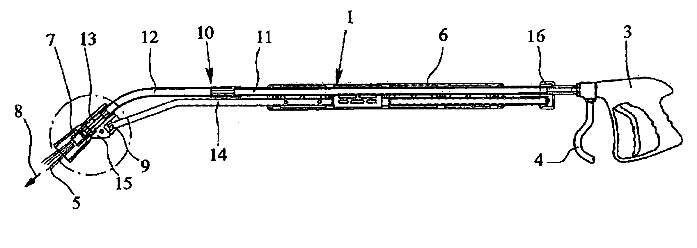
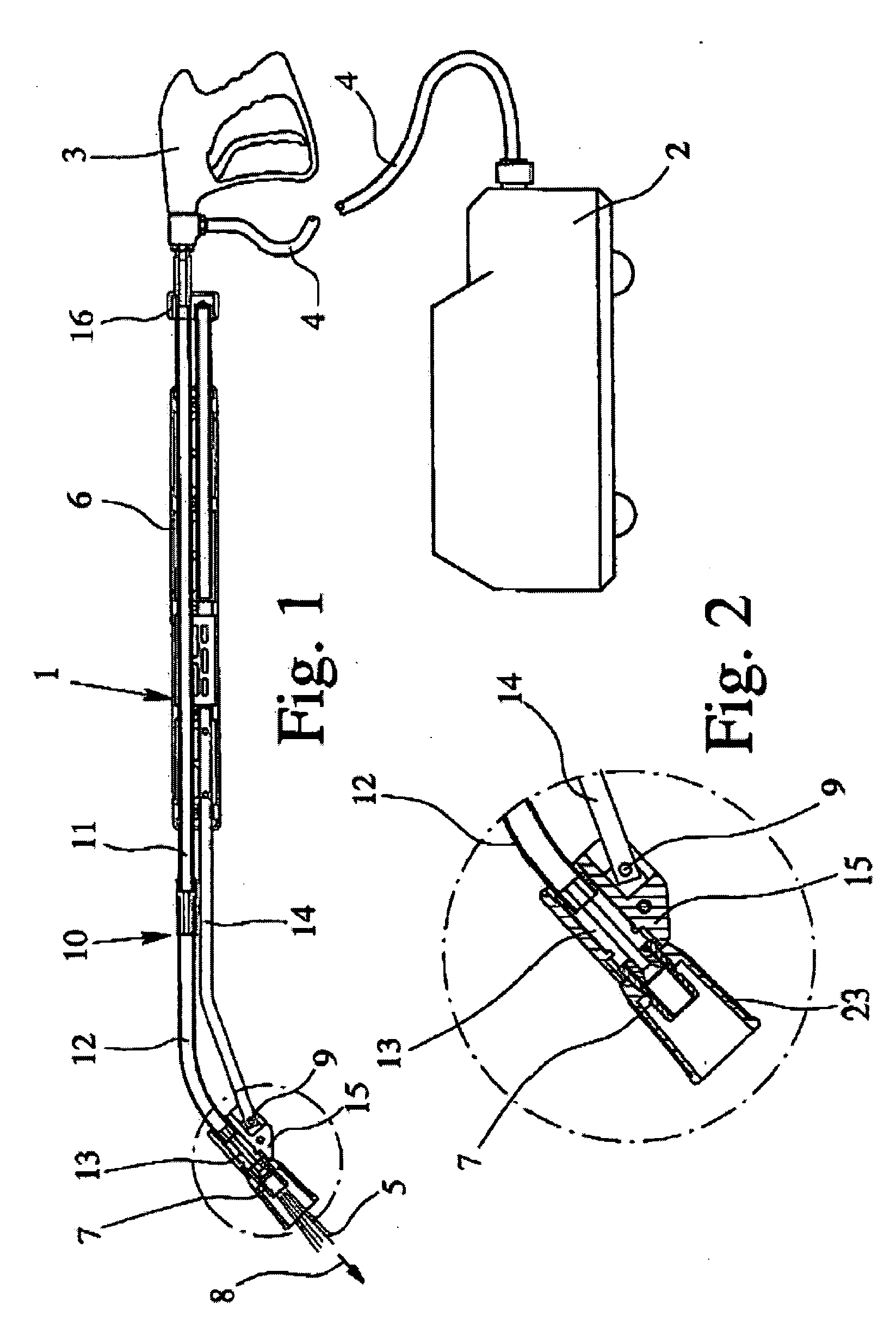
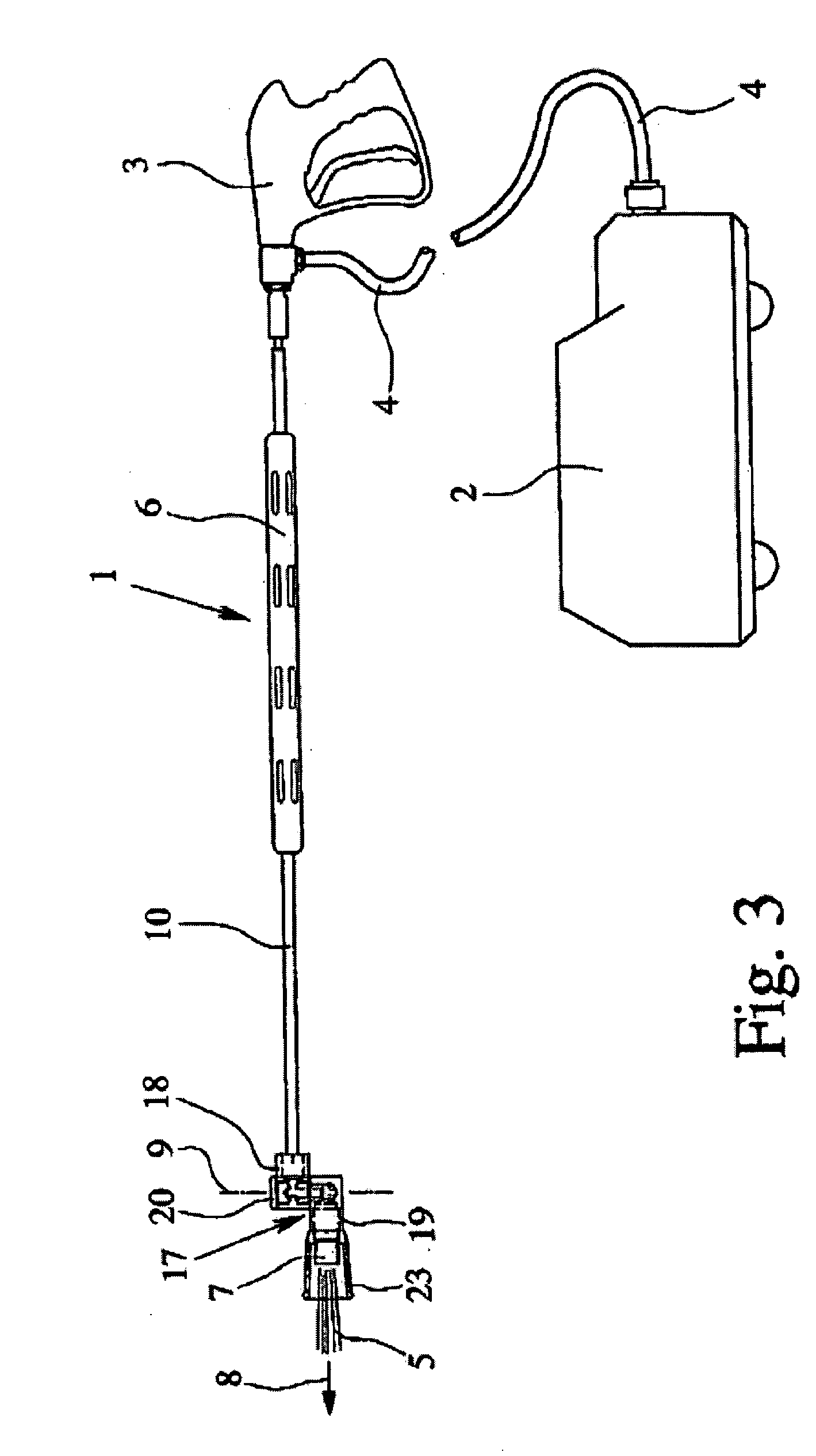
[0042]FIG. 3 shows the spray lance 1 with the handle 6, which is attached to the feed line 10, which leads to the nozzle 7. Here, the feed line 10 is preferably embodied as a rigid pipe, which is embodied either straight or optionally kinked.

[0043] According to the proposal, the nozzle 7 is attached via a link 17 to the feed line 10. Correspondingly, the nozzle 7 and thus the main spraying direction 8 can pivot about the pivoting axis 9, which runs transverse, especially perpendicular, to the longitudinal extension of the spray lance 1, the feed line 10, and / or the main spraying direction 8 of the nozzle 7.

[0044]FIG. 4 shows the link 17 in a perspective view without a feed line 10 and without nozzle 7.

[0045]FIG. 5 shows the link 17 in a schematic section along the longitudinal extension of the spray lance 1.

[0046] The link 17 is embodied in the shown example as a nozzle holder, because the nozzle 7 can be connected detachably to the link 17, thus, e.g., can be replaced for repai...

first embodiment

[0052] In the shown example, the two attachment parts 18, 19 can pivot by 360° relative to each other. However, the pivoting range of the link 17, thus of the two attachment parts 18, 19, can also be limited, preferably corresponding to the details on the

[0053] Instead of limiting the pivoting motion, the link 17 can also be embodied such that when a predetermined pivoting range is exceeded, especially when the two attachment parts 18, 19 approach a pivot position, in which they point in the same direction, the possible passage of cleaning fluid 5 in the link 17 is interrupted.

[0054] In addition, or as an alternative, to the mentioned pivoting limit, the nozzle 7 can also be surrounded by a so-called, preferably conical nozzle protector 23, which represents in the mounted state a pivoting limit, so that, in particular, the main spraying direction 8 can be prevented from pointing back towards the handle 6 parallel to the feed line 10.

[0055] The link 17 is preferably embodied such t...

third embodiment

[0059] In a schematic illustration, FIG. 6 shows the spray lance 1 according to the proposal. The spray lance 1 has in the region of its front or free end a support device 24 in order to be able to support the spray lance 1 on a floor surface 25 or the like.

[0060] The support device 24 can be embodied, e.g., as a sliding block or the like. In the shown example, the support device 24 has at least one roller or a wheel 26, preferably two wheels 26 spaced transverse to the longitudinal extension of the spray lance 1. An appropriate spacing of the wheels 26 provides good stabilization of the spray lance 1 against lateral tipping. The spray lance 1 can be held and guided very easily and with minimal expenditure of force just at the valve pistol 3.

[0061] In the shown example, the rotational axis runs preferably fixed, namely transverse, especially perpendicular, to the longitudinal extension of the spray lance 1. The rotational axis of the wheels 26 here also runs preferably transverse t...


PUM


Abstract

A spray lance for a high-pressure cleaning device is proposed with a pivoting nozzle and a support device, as well as an associated link for the spray lance. The spray lance according to the proposal permits universal applicability or easy adaptation to the particular conditions.

Description

FIELD OF THE INVENTION [0001] The present invention relates to a spray lance for a high-pressure cleaning device, especially for cleaning fluid. BACKGROUND OF THE INVENTION [0002] A high-pressure cleaning device in the sense of the present invention is known, e.g., from DE 196 17 778 C2. The high-pressure cleaning device has a feed pump for cleaning fluid. The cleaning fluid of a so-called cleaning or spray lance, which optionally has a valve pistol, can be fed via a pressure line preferably embodied as a hose. On its free end, the spray lance has a nozzle for discharging the cleaning fluid. The cleaning fluid is discharged especially as a stream with a fixed main spraying direction, even if the stream circulates or precedes around so-called rotary nozzles, e.g., for these rotary nozzles inclined to the main spraying direction, and therefore forms a conical spraying pattern. [0003] In practice, it has been shown that the typically elongated spray lance with fixed main spraying direc...

Claims


Application Information

Patent Timeline
IPC IPC(8): B05B1/28B05B1/30B05B9/00B05B9/01B05B15/06B05B15/652B08B3/02
CPCB05B1/28B05B1/3026B08B3/026B05B9/01B05B15/066B05B9/007B05B15/652
Inventor BOKE, THOMAS
Owner SUTTNER
Why Eureka
Try Eureka