Minimal resistance scallop for a well perforating device

a perforating device and minimal resistance technology, applied in the direction of fluid removal, drilling machine and method, borehole/well accessories, etc., can solve the problems of significant reduction of the structural strength of the carrier, failure to withstand external pressure exerted on the carrier, etc., to reduce the energy needed to exit, reduce the thickness of the carrier at the location of the scallop, and the effect of sufficient structural strength

Inactive Publication Date: 2005-06-30
MAULDIN SIDNEY WAYNE
View PDF6 Cites 22 Cited by
  • Summary
  • Abstract
  • Description
  • Claims
  • Application Information

AI Technical Summary

Benefits of technology

[0016] The present invention is an improvement for a well perforating device and method of manufacture to make a modification to the industry standard method of cutting a scallop on the outer surface of the hollow steel carrier that contains the perforating charges. The scallops are made at the location of each charge to reduce the energy needed to exit the carrier. The present invention is the use of an arching geometric cut for the scallop. The thickness of the carrier at the location of the scallop can be reduced while maintaining sufficient structural strength to withstand the pressures exerted on the carrier, as a result of the additional strength imparted from the arched geometric cut. The deeper arching geometric shape reduces the thickness of steel that the perforating jet must penetrate to exit the carrier which increases the remaining energy for greater penetration and hole size. Increasing the depth of cut of the scallop alone to the same thickness would result in significantly reduced structural strength of the carrier and failure to withstand the external pressures exerted on the carrier. The additional smaller geometric cut utilizes the additional strength created from the rigidity of the geometric cut to counter the effects of the reduced thickness.

Problems solved by technology

Increasing the depth of cut of the scallop alone to the same thickness would result in significantly reduced structural strength of the carrier and failure to withstand the external pressures exerted on the carrier.

Method used


Image

  • Minimal resistance scallop for a well perforating device
  • Minimal resistance scallop for a well perforating device
  • Minimal resistance scallop for a well perforating device

Examples


Embodiment Construction

[0029] In the following description, details of the present invention are given to provide an understanding of the present invention. However, those skilled in the art will know that the present invention may be practiced without these details and that numerous variations or modifications from the described embodiments are possible.

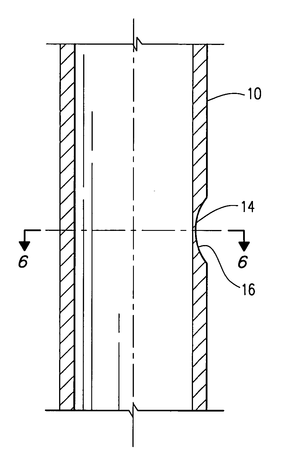
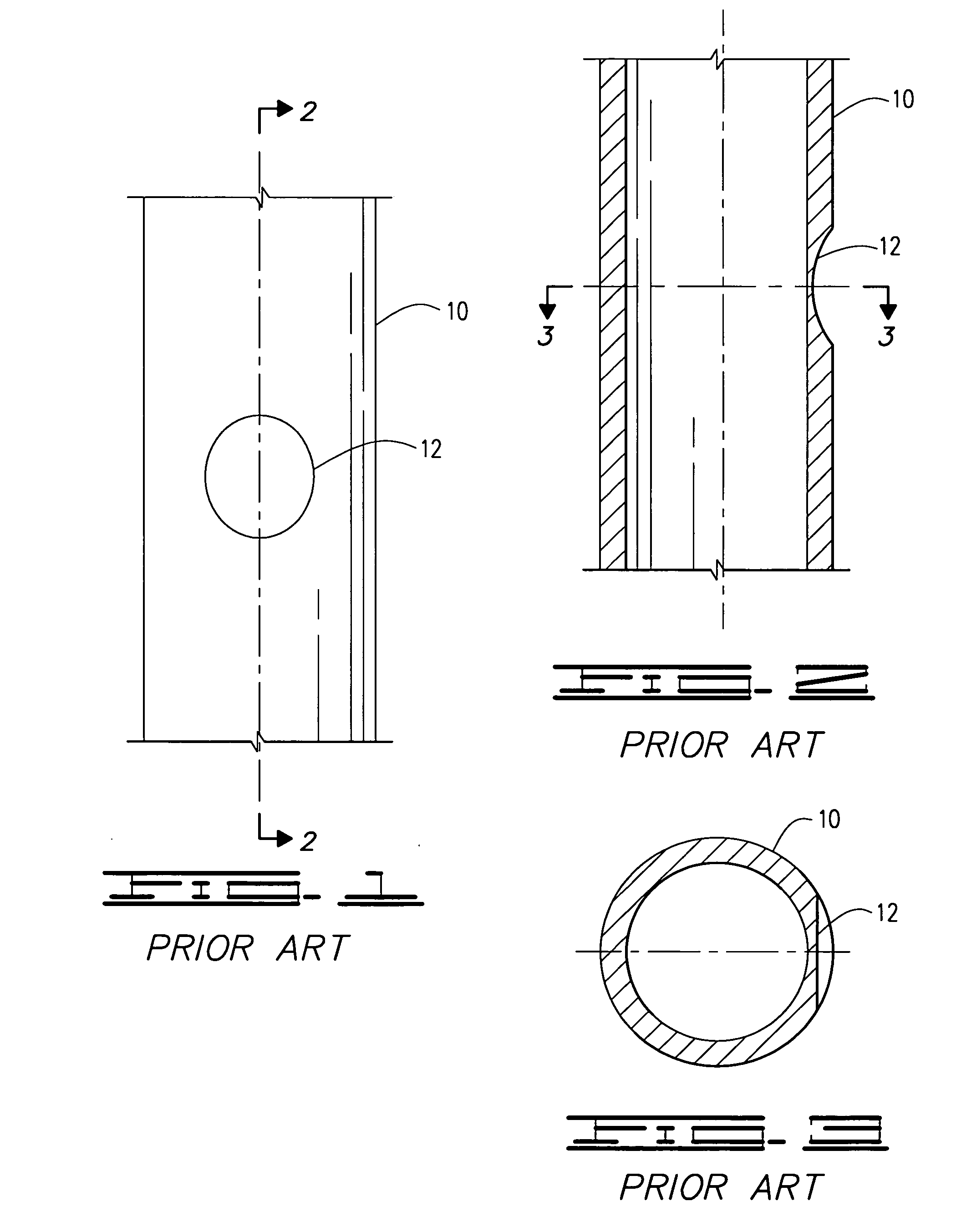
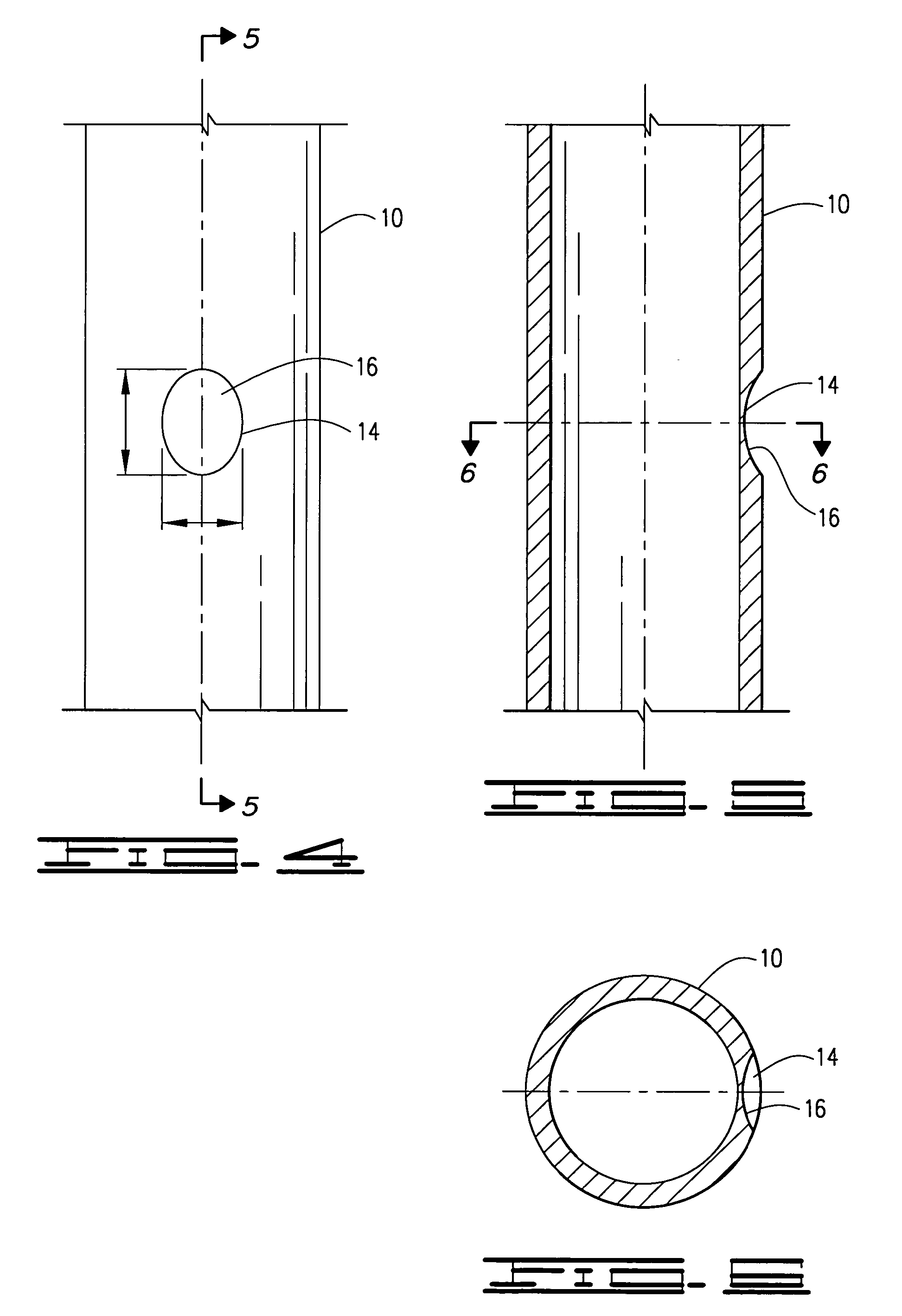
[0030] Recesses formed in the outer wall of a body member 10 are to enhance the performance of the shaped charge perforating jets or other explosives. The thinned area allows for less energy to exit the body member 10 and more energy to penetrate the rock formation. The preferred embodiments presented are shaped with geometric cuts to remove more steel, to improve performance, while utilizing the strength of the geometric cut to maximize the remaining strength of the body member 10 to withstand the hydrostatic pressures exerted by the wellbore fluids. One of the preferred embodiments is adding a geometric cut to the industry standard elliptical scallop 1...


PUM


Abstract

The present invention is an improvement in the design of a perforating gun to perforate the casing in oil and gas wells. Perforating guns have a cylindrical body member with explosive charges at specified intervals designed to shoot outwardly through the body member, the well casing, cement sheath, and into the rock formation. There are recessed areas, scallops, on the outer surface of the body member where the perforating jets, formed by the explosive charges, exit the body member. The present invention uses the strength of an arching geometric shape for the recessed area to be able to further reduce the thickness of steel for minimal resistance to the perforating jet. Minimizing the resistance to the perforating jet increases the depth of penetration into the rock formation and increases the hole size.

Description

CROSS-REFERENCE TO RELATED APPLICATIONS [0001] Not Applicable STATEMENT REGARDING FEDERALLY SPONSORED RESEARCH OR DEVELOPMENT [0002] Not Applicable REFERENCE TO A MICROFICHE APPENDIX [0003] Not Applicable BACKGROUND OF THE INVENTION [0004] The invention relates generally to an improvement in the design of an oil and gas well perforating device. The improvement applies to a type of perforating device that is typically lowered into the well through the casing or tubing in the well to a position where the explosive charges are detonated at the desired depth. The improvement is a method of modifying the scallop that is cut on the exterior of the device, at the location of a perforating charge, so as to minimize the resistance to the explosive charge which in turn improves the performance of the perforating charge by increasing its depth of penetration and hole size. [0005] After an oil or gas well is drilled, steel casing is lowered into the well and cemented to the adjoining rock forma...

Claims


Application Information

Patent Timeline
Patent Type & Authority Applications(United States)
IPC IPC(8): E21B43/116
CPCE21B43/116
Inventor MAULDIN, SIDNEY WAYNE
Owner MAULDIN SIDNEY WAYNE
Why Eureka
Try Eureka