High friction brake shoe assembly

Inactive Publication Date: 2005-06-30
FEDERAL MOGUL WORLD WIDE
View PDF27 Cites 7 Cited by
  • Summary
  • Abstract
  • Description
  • Claims
  • Application Information

AI Technical Summary

Benefits of technology

[0009] The invention relates to an emergency brake assembly comprising a rotating member operatively associated with a vehicular wheel. The rotating member (e.g., a wheel drum or rotor) has an engagement surface which forms the braking surface. A non-rotating brake element (e.g., either a brake shoe or pad) is positioned adjacent the rotating member and is movable between a brake applied condition in pressing contact with the engagement surface and a brake relaxed condition spaced from the engagement surface. The brake element includes a rigid backing plate and a friction material disposed on the backing plate. The friction material defines an outer surface opposing the engagement surface of the rotating member and

Problems solved by technology

For example, if the friction level generated by a friction brake is too low due to regions of the frictional matrix which are not in contact with the opposing friction surface of the brake drum or rotor, the brake will not function to the required level of static effectiveness, i.e. parking brake capability.
Such methods are prone to neglect by the average

Method used


Image

  • High friction brake shoe assembly
  • High friction brake shoe assembly
  • High friction brake shoe assembly

Examples


Embodiment Construction

[0027] The following detailed description illustrates the invention by way of example and not by way of limitation. The description clearly enables one skilled in the art to make and use the invention, describes several embodiments, adaptations, variations, alternatives, and uses of the invention, including what is presently believed to be the best mode of carrying out the invention.

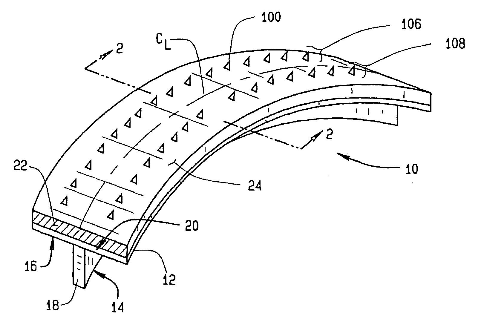
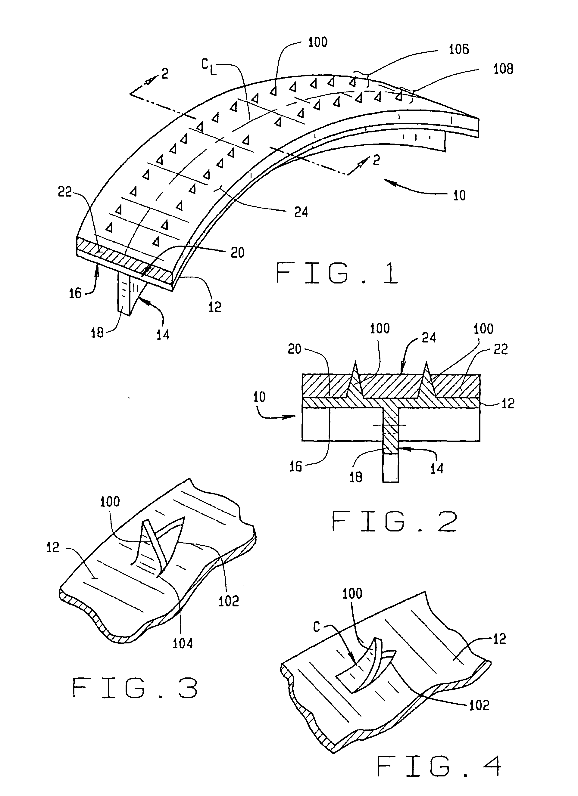
[0028] Turning to FIG. 1 a brake shoe assembly of the present invention is shown generally at 10. The brake shoe assembly 10 comprises a cylindrically curved brake shoe platform 12 defining a portion of a cylinder surface. The brake shoe assembly 10 is configured with one or more attachment points 14 on a lower surface 16 adapted to facilitate attachment of the brake shoe assembly 10 to a supporting structure on a motor vehicle wheel (not shown). The specific features of the attachment points 14 vary depending upon the particular application for which the brake shoe assembly 10 is intended.

[0029] For e...


PUM


Abstract

A vehicle brake shoe assembly (10) having a rigid backing plate (12) incorporating a plurality of extensions (100) which project through the brake friction material matrix (22) to the outer friction surface (24) of the brake shoe assembly (10). Each extension (100) is configured to cooperate with the brake friction material matrix (22) to engage a surface of an opposing friction element (28) simultaneously with the friction material (22), increasing the static and dynamic friction performance of the assembly (10) during initial use beyond that achieved from the application of either the brake friction material (22) or the projections (100) alone.

Description

CROSS-REFERENCE TO RELATED APPLICATIONS [0001] This is a Continuation-In-Part of U.S. Ser. No. 10 / 336,080, filed Jan. 3, 2003, now U.S. Pat. No. ______.BACKGROUND OF THE INVENTION [0002] The present invention relates generally to vehicle brake assemblies, and in particular, to a high friction brake assembly incorporating a plurality of backing plate extensions through a friction material matrix, to be utilized in vehicle parking brakes and vehicle emergency braking systems on vehicle equipped with a separate typical, full service brake system (disc or drum) at each of its four wheels. [0003] Vehicle drum type friction brakes commonly include a vehicle brake shoe assembly carrying a frictional matrix which is brought into contact with an inner cylindrical surface of a rotating brake drum to generate a frictional force and correspondingly slow, stop, or hold the vehicle in a stationary or parked position. Disc brake systems include a caliper assembly having opposing friction pads whic...

Claims


Application Information

Patent Timeline
IPC IPC(8): F16D65/08F16D69/00F16D69/04
CPCF16D65/0037F16D65/08F16D2069/0441F16D2069/002F16D2069/004F16D69/04F16D65/04
Inventor KULIS, STANLEY F. JR.COOK, CRAIG R.MUFFLEY, DAVID D.
Owner FEDERAL MOGUL WORLD WIDE
Why Eureka
Try Eureka