Protection circuit for power amplifier

a protection circuit and power amplifier technology, applied in the direction of amplifier protection circuit arrangement, amplifier with semiconductor devices only, amplifier with semiconductor devices, etc., can solve the problems of power amplifier breakdown, difficulty in configuration of variable load circuit, and inability of prior art electric power amplifying system to protect power amplifier from breakdown, etc., to achieve and gradual reduction of supply voltage provided to a power amplifier

Inactive Publication Date: 2005-06-30
COLLABO INNOVATIONS INC
View PDF12 Cites 9 Cited by
  • Summary
  • Abstract
  • Description
  • Claims
  • Application Information

AI Technical Summary

Benefits of technology

[0010] An object of the invention is to provide a protection circuit for power amplifier for preventing the breakdown of a power amplifier caused by a change in the operating conditions, such as load change, of the power amplifier, wherein its configuration is simple, no drop occurs in the output power of the power amplifier in normal operation, and a high electric power efficiency is obtained.

Problems solved by technology

Nevertheless, this prior art electric power amplifying system does not have the function of protecting the power amplifier from breakdown.
Thus, there has been a problem that certain power amplifier operating conditions such as a load change can cause breakdown to the power amplifier.
Nevertheless, in this method of changing the load of the power amplifier, the configuration of the variable load circuit is difficult.

Method used


Image

  • Protection circuit for power amplifier
  • Protection circuit for power amplifier
  • Protection circuit for power amplifier

Examples


embodiment 1

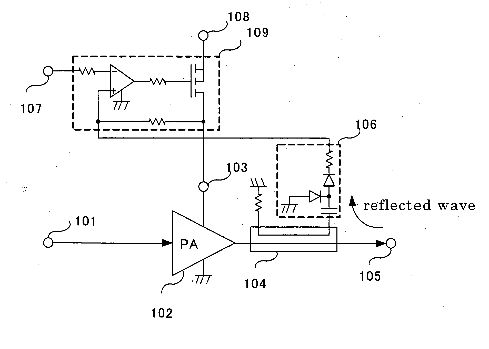
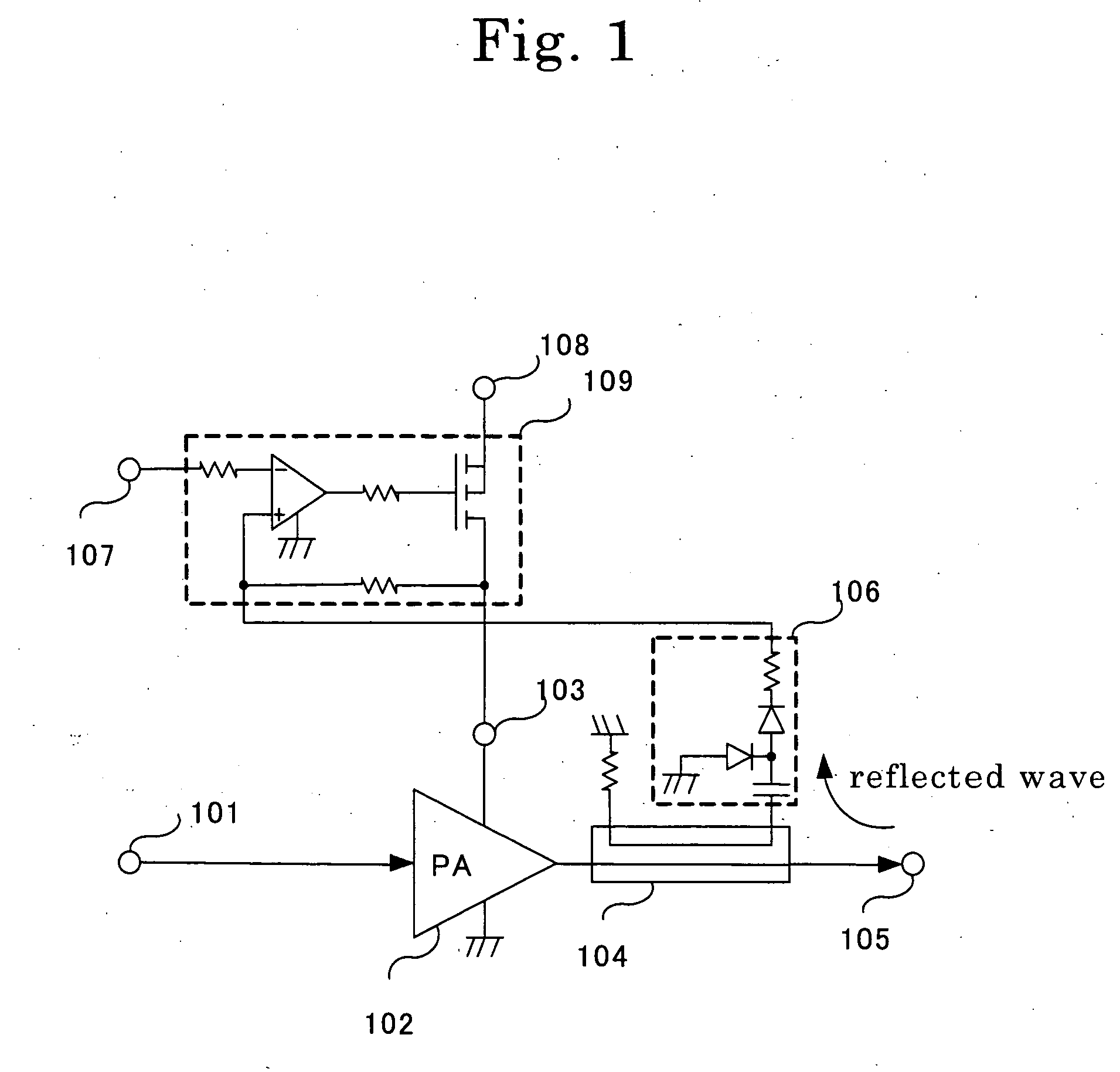
[0025]FIG. 1 is a block diagram showing the configuration of an electric power amplifying system containing a protection circuit for power amplifier according to Embodiment 1 of the invention. As shown in FIG. 1, the electric power amplifying system comprises an input terminal 101, a power amplifier 102, a power amplifier power supply terminal 103, a directional coupler 104, an output terminal 105, an electric power detector (such as a wave detector) 106, a power amplifier supply voltage control terminal 107, and a DC power supply terminal 108, as well as a power amplifier supply voltage control circuits 109 serving as supply voltage controlling means for varying a supply voltage supplied to the power amplifier 102. The part consisting of the directional coupler 104 and the electric power detector 106 corresponds to reflected wave power detecting means for detecting an increase in reflected wave power generated by impedance mismatching of a load connected to the power amplifier 102,...

embodiment 2

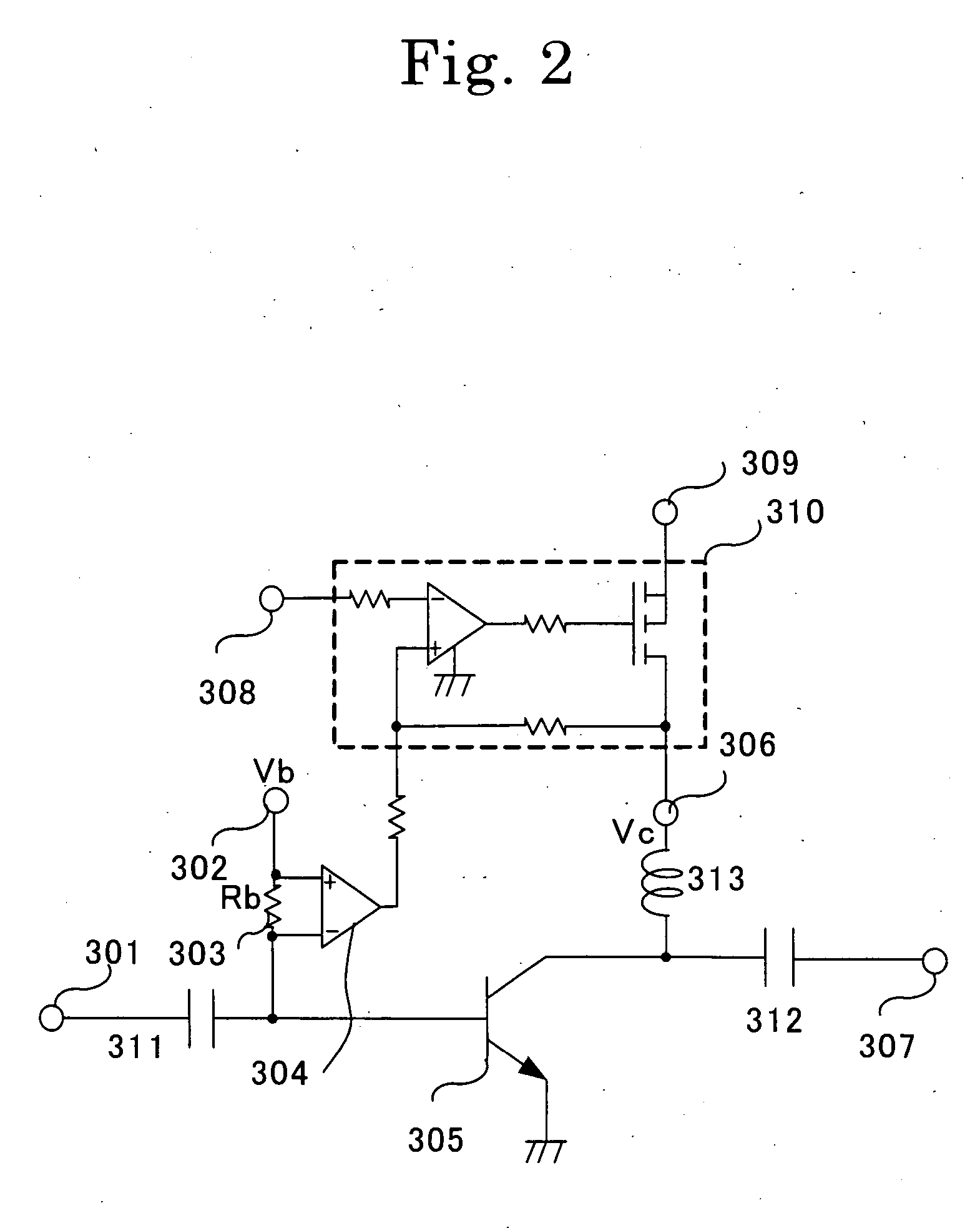
[0034]FIG. 2 is a block diagram showing the configuration of an electric power amplifying system containing a protection circuit for power amplifier according to Embodiment 2 of the invention. As shown in FIG. 2, the protection circuit for power amplifier comprises an input terminal 301, a base power supply terminal 302, a base resistor 303, a voltage conversion section 304, a bipolar transistor 305, a collector power supply terminal 306, an output terminal 307, a power amplifier supply voltage control terminal 308, a DC power supply terminal 309, a power amplifier supply voltage control circuit 310, capacitors 311 and 312, and an inductor 313. The part consisting of the base resistor 303 and the voltage conversion section 304 corresponds to current detecting means or breakdown condition detecting means for detecting an increase in a current flowing from the base power supply terminal 302 into the base of the bipolar transistor 305.

[0035] Described below is the operation of the ele...

embodiment 3

[0044]FIG. 3 is a block diagram showing the configuration of an electric power amplifying system containing a protection circuit for power amplifier according to Embodiment 3 of the invention. As shown in FIG. 3, the protection circuit for power amplifier comprises an input terminal 401, a gate power supply terminal 402, a gate resistor 403, a voltage conversion section 404, a field effect transistor 405, a drain power supply terminal 406, an output terminal 407, a power amplifier supply voltage control terminal 408, a DC power supply terminal 409, a power amplifier supply voltage control circuit 410, capacitors 411 and 412, and an inductor 413. The part consisting of the gate resistor 403 and the voltage conversion section 404 corresponds to current detecting means or breakdown condition detecting means for detecting an increase in the current flowing from the gate power supply terminal 402 into the gate of the field effect transistor 405.

[0045] Described below is the operation of...


PUM


Abstract

A directional coupler is provided on the output side of a power amplifier. An increase in reflected wave power from a load is detected through the directional coupler by an electric power detector (wave detector). Then, a detection signal of an electric power detector is provided to a power amplifier supply voltage control circuit. As a result, the supply voltage supplied to the power amplifier is reduced gradually. By virtue of this, the supply voltage provided to the power amplifier is gradually reduced when the power amplifier approaches a breakdown condition. This protects the power amplifier.

Description

BACKGROUND OF THE INVENTION [0001] 1. Field of the Invention [0002] The present invention relates to a protection circuit for power amplifier for preventing the breakdown of a power amplifier caused by a load change or the like in a high frequency power amplifier such as a mobile communications device. [0003] 2. Prior Art [0004] As shown in FIG. 4, a prior art electric power amplifying system comprises an input terminal 201, a power amplifier 202, a power amplifier power supply terminal 203, an output terminal 204, a power amplifier supply voltage control terminal 205, a DC power supply terminal 206, and a power amplifier supply voltage control circuit 207. [0005] A signal inputted through the input terminal 201 is amplified by the power amplifier 202, and then outputted through the output terminal 204. On the other hand, electric power to the power amplifier 202 is supplied through the power amplifier power supply terminal 203. At that time, the power amplifier supply voltage contr...

Claims


Application Information

Patent Timeline
Patent Type & Authority Applications(United States)
IPC IPC(8): H03F1/52
CPCH03F1/52
Inventor NAGATA, HIDEO
Owner COLLABO INNOVATIONS INC
Why Eureka
Try Eureka