Feedhorn, radio wave receiving converter and antenna

a radio wave receiving converter and feedhorn technology, applied in the direction of leaky waveguide antennas, basic electric elements, antennas, etc., can solve the problems of reducing the yield of the dielectric member, and affecting the operation of the feedhorn. the effect of reducing the increase in manufacturing costs

Inactive Publication Date: 2005-06-30
SHARP KK
View PDF4 Cites 21 Cited by
  • Summary
  • Abstract
  • Description
  • Claims
  • Application Information

AI Technical Summary

Benefits of technology

[0009] An object of the present invention is to provide a feedhorn, a radio wave receiving converter and an antenna that can suppress an increase in manufacturing costs.

Problems solved by technology

However, the aforementioned dielectric member formed of a thick dielectric involves a problem that, when performing injection molding, a concave portion (a sinkmark generating portion) is generated at the outer portion thereof, or a bubble is generated in the inner portion thereof.
Additionally, generation of such a concave portion or a bubble in the dielectric member also involves a problem that the radiation pattern characteristics of a feedhorn using the dielectric member is distorted (the radiation pattern characteristics deviate from the designed characteristics).
As a result, the dielectric member with a concave portion or a bubble is treated as a defective, and thus becomes a cause of reducing yield of the dielectric member.
Additionally, since a step of screening such a defective is required, the manufacturing period is prolonged.
As a consequence, it has been one cause of increasing the manufacturing costs of the dielectric member (and hence, the feedhorn).

Method used


Image

  • Feedhorn, radio wave receiving converter and antenna
  • Feedhorn, radio wave receiving converter and antenna
  • Feedhorn, radio wave receiving converter and antenna

Examples


first embodiment

[0030] Referring to FIGS. 1-3, a converter including a dielectric feedhorn and a radio wave receiving antenna (hereafter also referred to as an antenna) according to the present invention will be described.

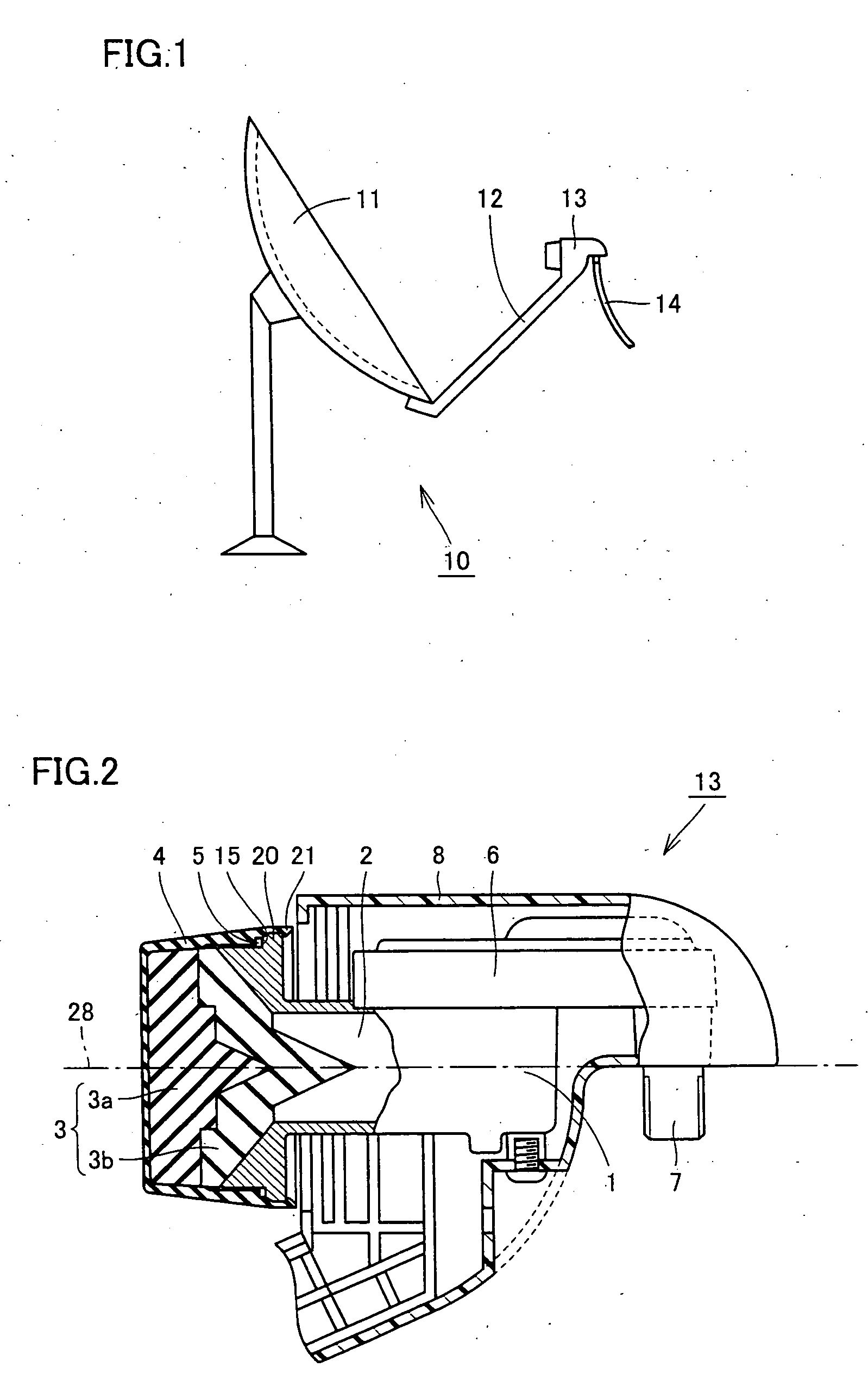
[0031] As shown in FIG. 1, an antenna 10 according to the present invention includes a parabolic portion 11 for reflecting a radio wave, an arm 12 connected to parabolic portion 11, and a converter 13 arranged at the tip of arm 12 for receiving the radio wave. To converter 13, a cable 14 is connected for transmitting the received radio wave (a signal) to other devices such as a tuner or a BS receiver. As this cable 14, for example a coaxial cable can be used. To the back side of parabolic portion 11, a support arm, which is a fixing support member for fixedly arranging antenna 10 in a prescribed position, is mounted.

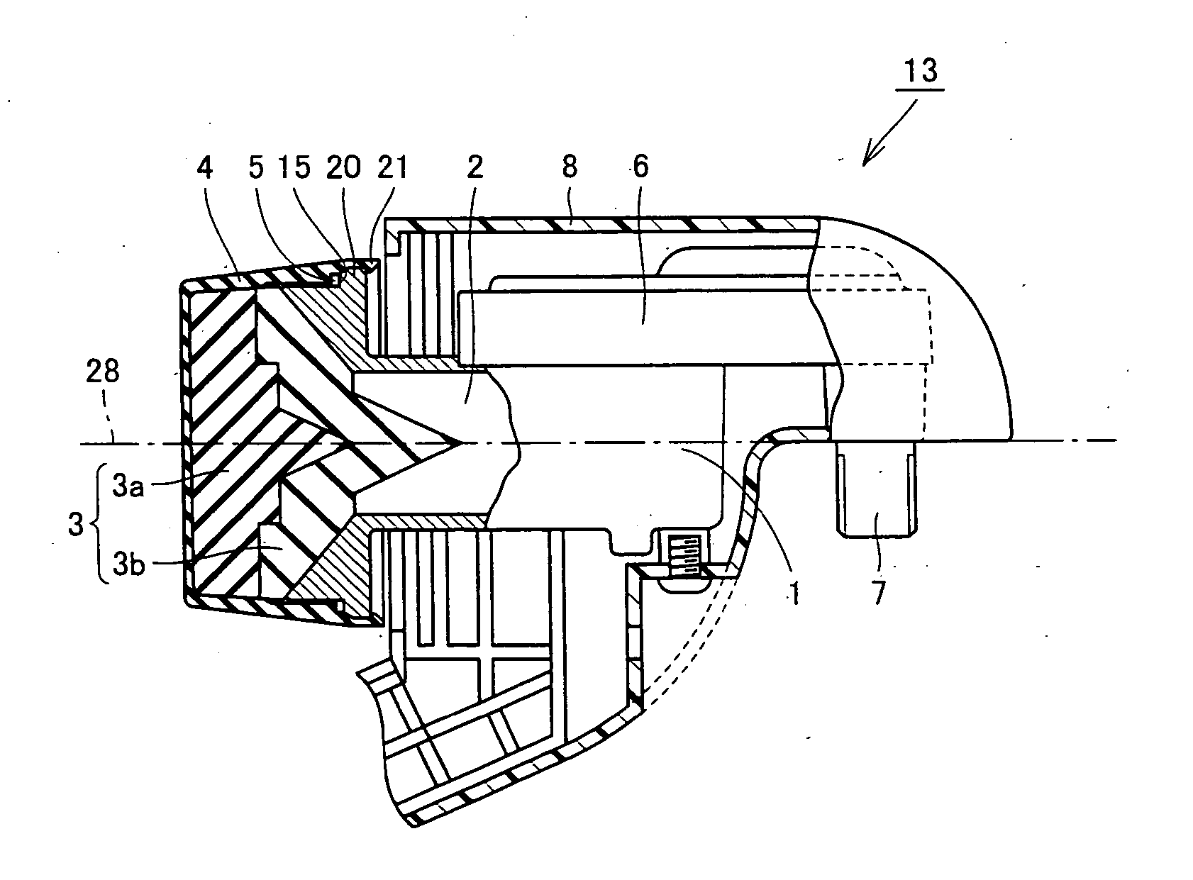
[0032] As shown in FIG. 2, converter 13 is formed of chassis body 1, a circuitry portion 6 connected to chassis body 1, a dielectric member 3 arranged to close an op...

second embodiment

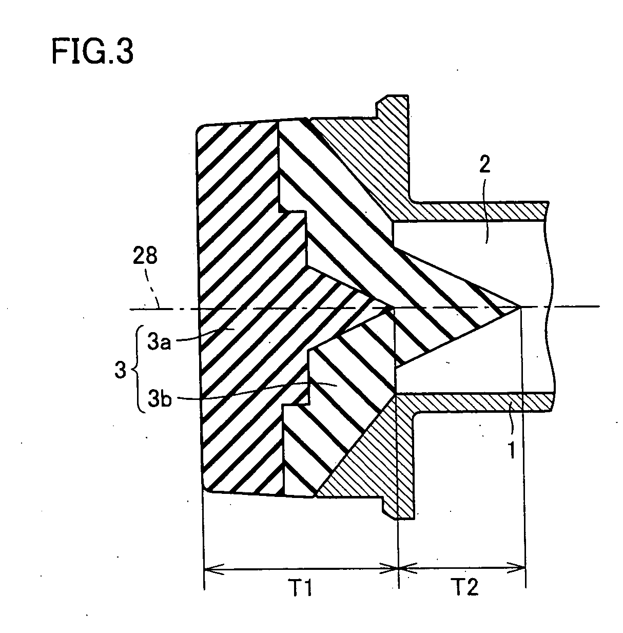
[0066] Referring to FIG. 13, a second embodiment of a converter according to the present invention will be described. FIG. 13 corresponds to FIG. 3.

[0067] While the converter including a dielectric feedhorn shown in FIG. 13 basically has the same structure as converter 13 shown in FIGS. 1-3, they are different in the structure of dielectric member 3. Specifically, in the converter shown in FIG. 13, dielectric member 3 is constituted by three members of dielectrics 53a-53c. In particular, dielectric 53c has a ring-like shape. Dielectric 53b is formed of a center portion 55 that is inserted into a center hole 54 of this ring-like dielectric 53c, and a circumferential outer edge portion 56 arranged from this center portion 55 relative to center axis 39 to be spread in a radial manner from center portion 55. Dielectric 53a is formed of a center portion 58 that is inserted into a hole 57 formed at a center portion of dielectric 53b, and an outer edge portion 59 connected to this center ...


PUM


Abstract

A dielectric feedhorn as a feedhorn according to the present invention, with which a feedhorn, a radio wave receiving converter and an antenna capable of suppressing an increase in manufacturing costs can be obtained, includes a chassis body including a waveguide having an opening, and a dielectric member. The dielectric member is connected to the opening of the waveguide, and constituted by dielectrics as a plurality of members.

Description

[0001] This nonprovisional application is based on Japanese Patent Application No. 2003-433373 filed with the Japan Patent Office on Dec. 26, 2003, the entire contents of which are hereby incorporated by reference. BACKGROUND OF THE INVENTION [0002] 1. Field of the Invention [0003] The present invention relates to a feedhorn, a radio wave receiving converter and an antenna, and particularly, to a feedhorn including a dielectric, a radio wave receiving converter and an antenna. [0004] 2. Description of the Background Art [0005] Conventionally, an antenna for receiving a radio wave of satellite broadcasting or the like is known. To the antenna, a radio wave receiving converter is arranged. As a member constituting the radio wave receiving converter, a feedhorn in which a dielectric is connected to an open end of a waveguide is known (for example, see Japanese Patent Laying-Open No. 2001-217644). [0006] According to Japanese Patent Laying-Open No. 2001-217644, a dielectric member const...

Claims


Application Information

Patent Timeline
Patent Type & Authority Applications(United States)
IPC IPC(8): H01Q19/13H01Q1/02H01Q13/02H01Q13/24
CPCH01Q19/08H01Q13/0266
Inventor NAGANO, ATSUSHIOKABE, YOSUKE
Owner SHARP KK
Why Eureka
Try Eureka