Ink jet printing apparatus, ink jet printing method and print head

a printing apparatus and ink jet technology, applied in the direction of printing and inking apparatus, etc., can solve the problems of increasing cost, elongating the print head with high-density nozzles, and requiring ink droplets to be absorbed from the nozzles of the print head unit, and achieves low cost and high speed.

Inactive Publication Date: 2005-06-30
CANON KK
View PDF16 Cites 21 Cited by
  • Summary
  • Abstract
  • Description
  • Claims
  • Application Information

AI Technical Summary

Benefits of technology

[0014] An object of this invention is to provide an elongate print head which can print a high-quality image with no density variation-caused lines at high speed and which can be manufactured at low cost and with ease and to provide an ink jet printing apparatus and an ink jet printing method using this print head.

Problems solved by technology

However, the ink jet printing apparatus using the elongate print head with high-density nozzles has the following problems.
First, in the above system if an image in a print area is to be completed in one printing scan (one pass) or in a small number of passes, ink droplets ejected from the nozzles of print head units need to be absorbed and fixed in the print medium in a short period of time.
This in turn increases cost and reduces the print density or pixel density, degrading the quality of the printed image.
Second, if the nozzles are arrayed at high density in a single line, ink droplets ejected from the adjoining nozzles may merge together on the print medium into an inappropriate shape.
When an image to be printed has a high duty, the ink that failed to be absorbed in the print medium may remain on the print medium in a liquid state, degrading the print quality.
Third, ink dots formed by those nozzles in a boundary portion between the nozzle groups may produce artifacts such as streaking caused by optical density variations which shows up in the form of white or black lines, degrading a print quality.
In an ink jet printing apparatus using the above print head having a plurality of longitudinally connected nozzle groups, however, a problem has been observed.

Method used


Image

  • Ink jet printing apparatus, ink jet printing method and print head
  • Ink jet printing apparatus, ink jet printing method and print head
  • Ink jet printing apparatus, ink jet printing method and print head

Examples


first embodiment

of this Invention

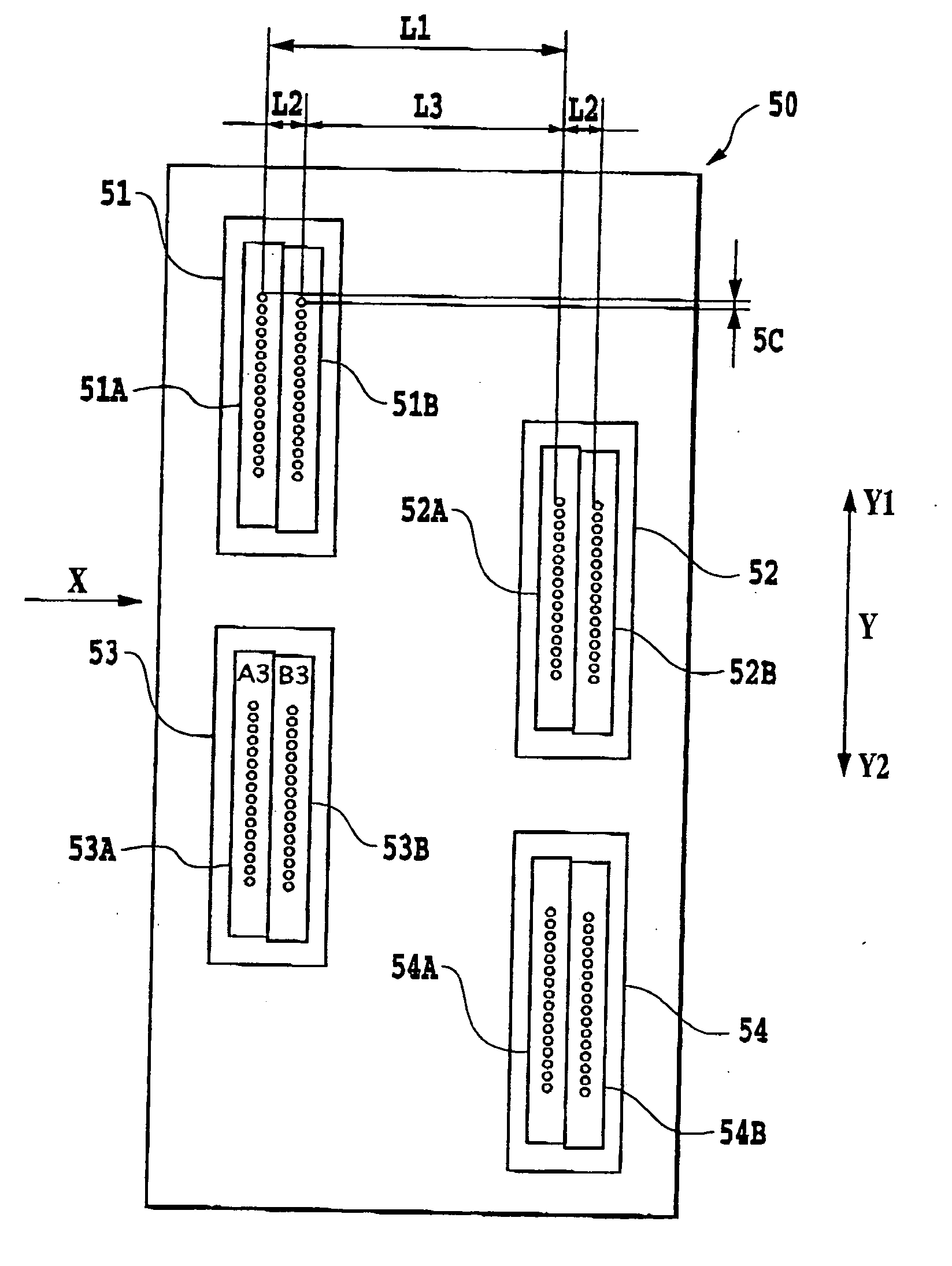
[0071] To solve these problems experienced with the related technologies described above, the first embodiment of this invention provides a print head constructed as shown in FIG. 9 for use in the full-line type ink jet printing apparatus of FIG. 1.

[0072] In FIG. 9, reference numbers 81, 82, 83, 84 represent nozzle groups each made up of an odd-numbered nozzle array and an even-numbered nozzle array. These nozzle groups are alternately shifted to different positions in the X direction, i.e., to upstream and downstream side, and connected at their ends in the Y direction, thus forming an elongate print head 80 extending in the Y direction. Of these nozzle groups, the nozzle groups 81, 83 are situated in the same upstream position with respect to the X direction and the nozzle groups 82, 84 are likewise situated in the same downstream position with respect to the X direction. While in FIG. 9 the elongate print head 80 is shown to have four nozzle groups 81-84, it is ...

second embodiment

of this Invention

[0083] Next, a second embodiment of this invention will be explained by referring to FIG. 10.

[0084] A print head 90 in the second embodiment is an elongate print head which, as in the first embodiment, has a plurality of nozzle groups of the same construction (four nozzle groups 91, 92, 93, 94) arranged staggered. It is noted, however, that two nozzle arrays making up each nozzle group differ from those of the first embodiment.

[0085] Let us take a nozzle group 91 for example. Nozzle arrays 91A, 91B in the nozzle group 91 each have their nozzles arranged staggered.

[0086] The nozzle array 91A has nozzle array forming elements 91A1, 91A2 arrayed in a staggered manner along two parallel limes a small distance L4 apart in the X direction. Like the nozzle array 91A, the nozzle array 91B has two lines of nozzle array forming elements 91B1, 91B2 and is arranged parallel to the nozzle array 91A. In each of these nozzle arrays the nozzles are arranged at a pitch of 9B. Fur...

third embodiment

of this Invention

[0094]FIG. 11 shows a third embodiment of this invention. A print head 100 shown here has two sets of those nozzle groups used in the first embodiment of FIG. 9 arranged side by side in the X direction. With this arrangement, the similar effect to that of the above embodiments can be expected and adjoining dots stably form merged dots of the shape of FIG. 13A.


PUM


Abstract

An ink jet print head is provided which can print a high-quality image with no density variation-caused lines at high speed and which can be manufactured at low cost and with ease. For this purpose, the print head of this invention has a plurality of nozzle groups each having at least one nozzle array arranged in a predetermined array direction Y crossing a relative motion direction X. A distance in the relative motion direction between the nozzles in each nozzle group adjoining each other in the array direction Y is set almost equal to a distance in the relative motion direction between the nozzle groups adjoining each other in the array direction Y.

Description

BACKGROUND OF THE INVENTION [0001] 1. Field of the Invention [0002] The present invention relates to an Ink jet print head having nozzles densely arrayed therein to eject ink containing a colorant, and to an ink jet printing apparatus and an ink jet printing method to form an image using the print head. More specifically, the present invention relates to an ink jet printing apparatus and an ink jet printing method using an elongate print head which has a plurality of nozzle groups each made up of a array of nozzles arranged staggered between two parallel lines, one on an upstream side and the other on a downstream side with respect to a direction in which a print medium is moved relative to the print head. Particularly, this invention relates to an ink jet printing method, an ink jet printing apparatus and a print head suited for a so-called one-pass printing in which the elongate print head Is scanned only once over a print area to complete a printed image. [0003] This invention is...

Claims


Application Information

Patent Timeline
Patent Type & Authority Applications(United States)
IPC IPC(8): B41J2/045B41J2/055B41J2/15B41J2/155B41J2/515
CPCB41J2/15B41J2202/20B41J2/515B41J2/155
Inventor SHIBATA, TSUYOSHIKARITA, SEIICHIROOGINO, HIROYUKI
Owner CANON KK
Why Eureka
Try Eureka