
Apparatus and method for processing informational signal

a technology of informational signal and apparatus, applied in the direction of signal generators with optical-mechanical scanning, instruments, television systems, etc., can solve the problem of preventing the acquisition of an hd signal adapting to the image display devi

Inactive Publication Date: 2005-06-30
SONY CORP
View PDF3 Cites 4 Cited by
  • Summary
  • Abstract
  • Description
  • Claims
  • Application Information

AI Technical Summary

Benefits of technology

[0022] As described above, according to the present invention, values of the multiple items of informational data of the first informational signal located around the target position in the second informational signal are converted based on the correspondence relation between the value of the informational data in the output means for obtaining the output by the second informational signal and the output value so as to obtain plural output values. A class to which the informational data of the target position in the second informational signal belongs is detected based on the plural output values so as to generate the informational data of the target position in the second informational signal corresponding to this class. This allows appropriate classification for the output characteristic of the output means to be performed, thereby obtaining the second informational signal fitting to the output means.

Problems solved by technology

That is, in the apparatus for converting the image signal disclosed in the Japanese Patent Application Laid-Open No.2001-309315, the classification is executed in the same way regardless of the kinds of the image display devices so that classification inadequate to fit to an output characteristic of a used image display device is carried out.
This prevents an HD signal adapting to the image display device from being obtained.

Method used


Image

  • Apparatus and method for processing informational signal
  • Apparatus and method for processing informational signal
  • Apparatus and method for processing informational signal

Examples


Embodiment Construction

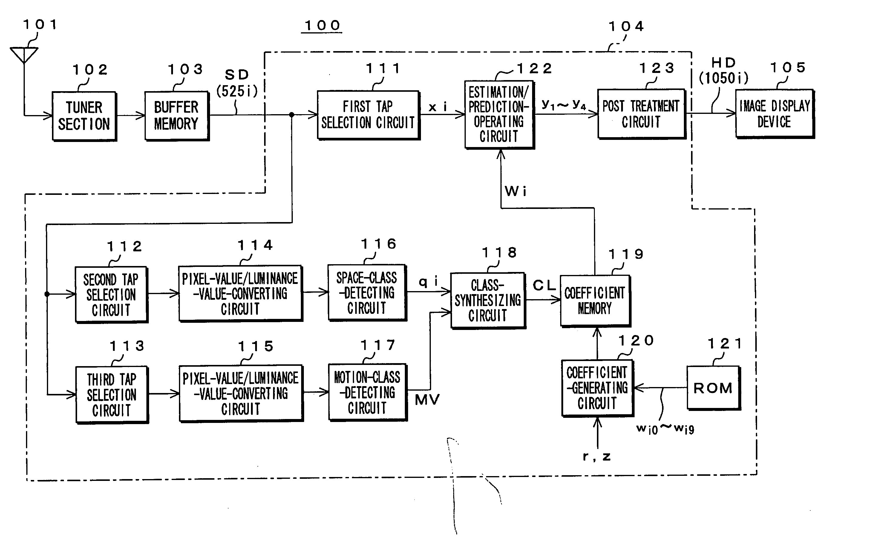
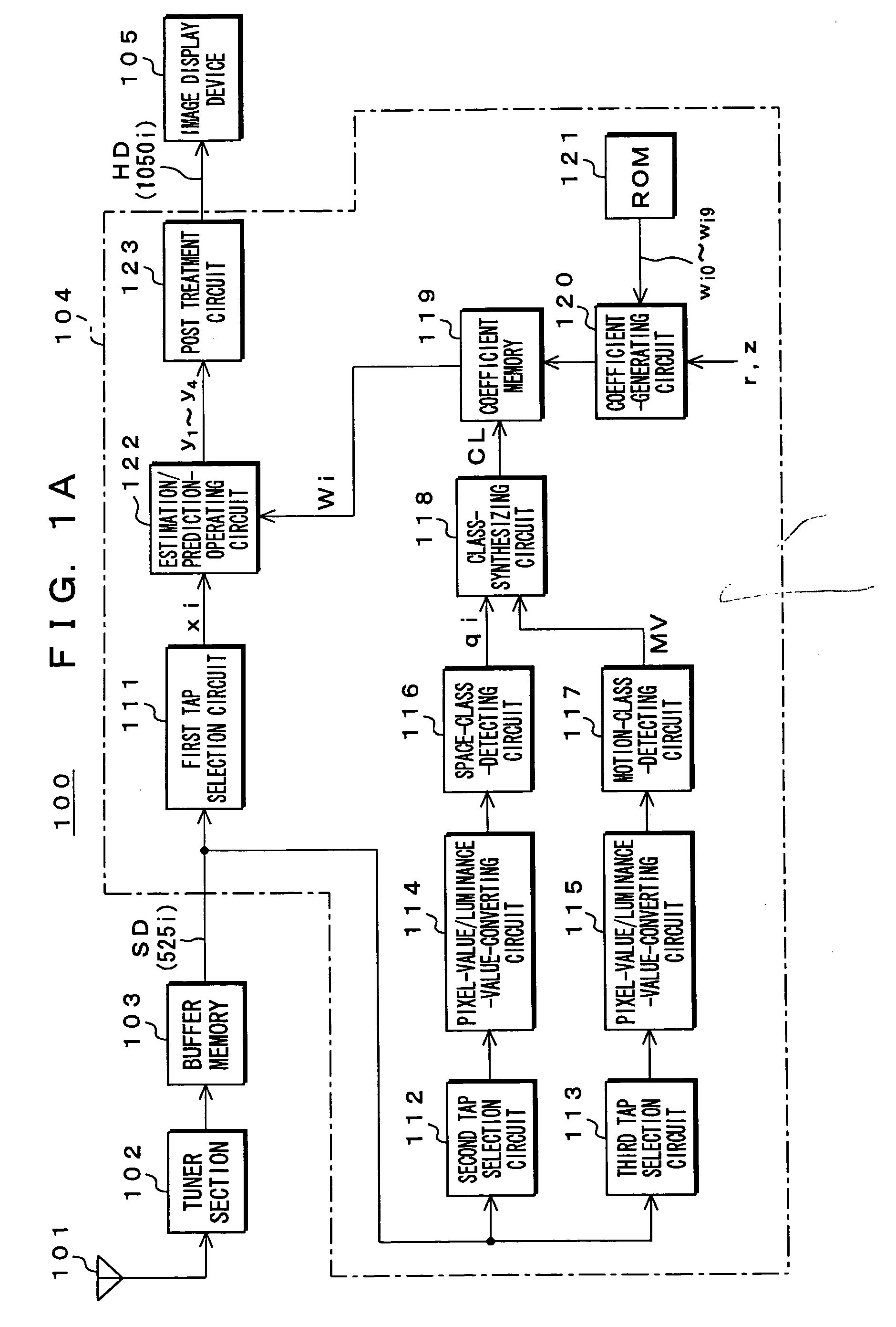
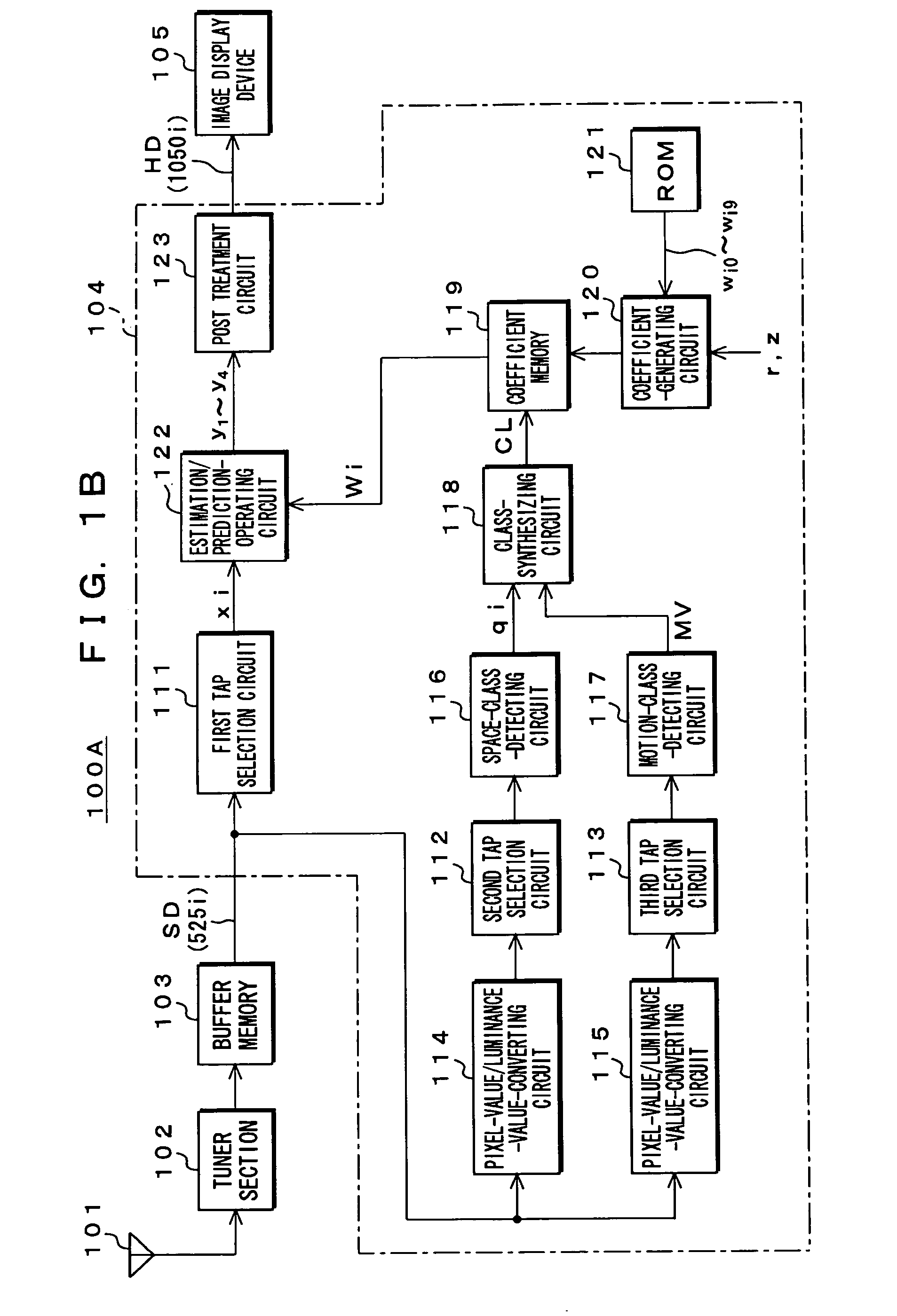
[0044] Hereinafter, the preferred embodiments of the present invention will be described in detail with reference to the accompanying drawings. FIG. 1A shows a configuration of a TV receiver 100 according to an embodiment of the present invention. FIG. 1B shows a configuration of a TV receiver 100A according to another embodiment of the present invention.

[0045] This TV receiver 100 has a function of obtaining a standard definition (SD) signal called as 525i signal from a broadcasting signal, converting this 525i signal to a high definition (HD) signal called as 1050i signal, and displaying an image composed of this HD signal. The 525i signal mentioned here is an interlace type image signal having 525 lines. The 1050i signal mentioned here is an interlace type image signal having 1050 lines.

[0046]FIG. 2 shows the relation in pixel position of a frame (F) in which the 525i signal and 1050i signal exist, while the pixel position of an odd (o) field is indicated with a solid line and ...


PUM


Abstract

Converting circuits convert the values of multiple items of SD pixel data (pixel value) as class tap data to luminance values. The converting circuits convert pixel values to luminance values based on a correspondence relation between a value of pixel data in an image display device and a luminance value. Class-detecting circuits detect a space class and a motion class based on plural luminance values. Class-synthesizing circuit acquires a class code indicating the class to which the pixel data of a target position in an HD signal belongs. Estimation / prediction-operating circuit obtains items of pixel data of the target position in the HD signal based on an estimation equation using data of an prediction tap and coefficient data of the class indicated by the class code. Consequently, appropriate classification of class to the luminance characteristic of a display device is performed.

Description

BACKGROUND OF THE INVENTION [0001] 1. Field of the Invention [0002] The present invention relates to an apparatus and a method for processing informational signal. More specifically, the present invention relates to an apparatus and a method for processing informational signal, which converts a first informational signal composed of multiple items of informational data to a second informational signal composed of multiple items of informational data, an apparatus and a method for generating coefficient seed data, which are used in the apparatus and the method for processing informational signal, a program for executing each of the methods, and a medium recording the program thereof. [0003] 2. Description of Related Art [0004] Conventionally, a format conversion for converting, for example, a standard definition (SD) signal called as 525i signal to a high definition (HD) signal called as 1050i signal has been proposed. The 525i signal designates an interlace type image signal having ...

Claims


Application Information

Patent Timeline
Patent Type & Authority Applications(United States)
IPC IPC(8): G09G5/10H04N5/202H04N7/01
CPCH04N7/0125H04N7/0145H04N7/0137H04N7/01
Inventor KONDO, TETSUJIROASAKURA, NOBUYUKINISHIKATA, TAKEHARUFUJISHIMA, KOICHI
Owner SONY CORP
Learn More