Tire pressing assembly machine

A technology of tires and racks, which is applied in the field of tire pressing and assembly machines, can solve the problems of shortening production time, slow production speed, and long time consumption, and achieve the effects of shortening production time, reducing waste, and improving work efficiency

Inactive Publication Date: 2020-12-18
殷学锋
View PDF0 Cites 0 Cited by
  • Summary
  • Abstract
  • Description
  • Claims
  • Application Information

AI Technical Summary

Problems solved by technology

[0005] In order to overcome the shortcomings of long time consumption, slow production speed, wasting a lot of manpower, and high requirements on people's physical fitness, the technical problem to be solved is to provide a plastic that shortens production time, speeds up production, and saves manpower. Inner drum solid tire pressing assembly machine

Method used


Image

  • Tire pressing assembly machine
  • Tire pressing assembly machine
  • Tire pressing assembly machine

Examples


Embodiment 1

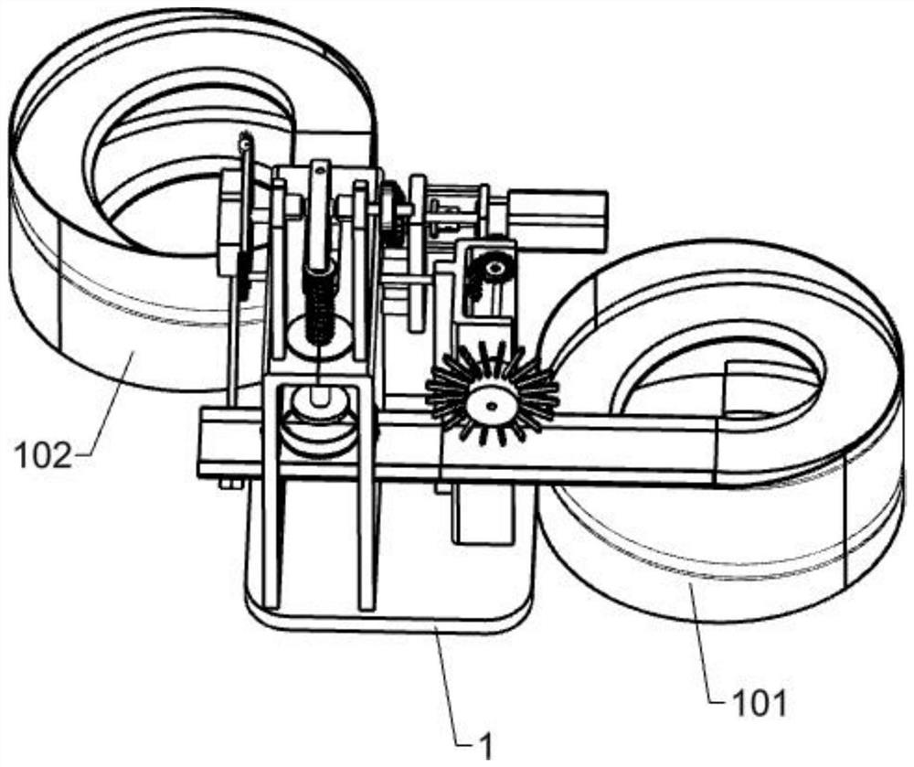
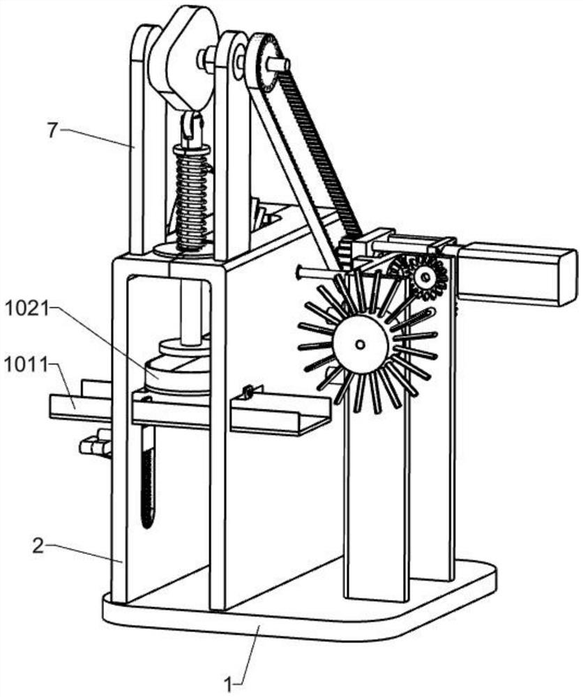
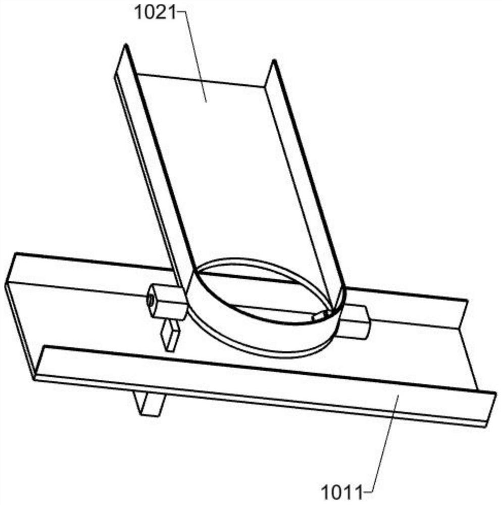
[0027] A tire press assembly machine, such as Figure 1-5 , Figure 7 As shown, it includes base (1), vibration plate one (101), vibration plate two (102), transmission plate one (1011), transmission plate two (1021), frame (2), installation plate one (3) , motor (4), shaft one (5), timing pulley one (6), mounting plate two (7), shaft two (8), timing pulley two (9), timing belt (901), cam One (10), pressure bar (11), spring one (1101) and pressure pad (12), base (1) top is fixedly installed with frame (2), and the top of frame (2) both sides is connected and fixedly installed with transmission Plate one (1011), the left end of vibration plate one (101) is fixedly connected with the right end of transmission plate one (1011), and transmission plate two (1021) is fixedly installed on the frame (2) near the side of transmission plate two (1021), The second transmission plate (1021) is perpendicular to the first transmission plate (1011), the rear end of the vibration plate two ...

Embodiment 2

[0030] On the basis of Example 1, such as Image 6 As shown, the locking mechanism (a) includes a casing (a01), a thimble (a02), a spring two (a03) and an inclined block (a04). In the groove, the thimble (a02) is slidably connected in the shell (a01), and the inside end of the thimble (a02) is fixedly connected with a slanting block (a04), and the second spring (a03) is sleeved on the shell (a01).

[0031] The setting of the locking mechanism (a) is to ensure that the tire will not fall directly when it is sent to the designated position, which will affect the normal operation of the device. When the tire is sent to the designated position, the inclined block in the locking mechanism (a) will (a04) will hold the tire to prevent the tire from falling before pressing down. When the pressure rod (11) and the pressure pad (12) are pressed down, it will squeeze the inclined block (a04) to move outward, and drive the thimble (a02) ) to move outward, and after the tire is successful...

Embodiment 3

[0033] On the basis of Example 2, such as Image 6 , Figure 9 , Figure 10As shown, it also includes support two (13), shaft three (14), toothless tooth disc (15), shaft four (16), spur gear one (17), pulley one (18) and soft rubber Rod one (181), bracket two (13) are fixedly installed on the frame (2) near the right side of the motor (4), the right end of the shaft rod three (14) is fixedly connected with the shaft rod one (5) left end, and the shaft rod three (5) left end is fixedly connected. The left end of (14) is fixedly installed with tooth-missing chainring (15), shaft four (16) is rotatably connected in the frame (2), shaft four (16) is positioned at the back of mounting plate two (7), shaft Four (16) are fixedly equipped with a spur gear one (17) near the left end of the tooth-missing chainring (15), and the spur gear one (17) meshes with the tooth-missing chainring (15). Pulley one (18), a plurality of soft rubber sticks one (181) are distributed in array on the...


PUM


Abstract

The invention relates to an assembly machine, in particular to a tire pressing assembly machine. The technical problems to be solved is to provide a plastic inner drum solid tire pressing assembly machine which can shorten the production time, increase the production speed and save manpower at the same time. According to the technical implement scheme, the tire pressing assembly machine comprisesa base, a first vibration disk, a second vibration disk, a first conveying plate, a second conveying plate, a rack, a first mounting plate, a motor, a first shaft rod, a first synchronous belt wheel,a second mounting plate and the like. The rack is fixedly installed on the base. The first conveying plate is fixedly installed on the rack. The first vibration disk is fixedly connected with the first conveying plate. According to the tire pressing assembly machine, the motor is started to replace manpower, waste of human physical strength is reduced, an automatic conveying device is structurallyadded, the overall production process is accelerated, the production time is shortened, and the working efficiency is improved.

Description

technical field [0001] The invention relates to an assembly machine, in particular to a tire pressing assembly machine. Background technique [0002] With the rapid development of the transportation industry, people have a rapid demand for travel tools, and the demand for tires has also risen sharply. Tires are composed of outer rubber tires and hubs, and are mainly used for travel tools such as bicycles, buses, cars and trucks. [0003] In the production of traditional crafts, the processing of tires and wheels is done manually, and the tires are pressed into the wheels. In the production of such a large demand for tires, the traditional manual methods are obviously unable to keep up. The traditional production method not only consumes The time is long, the production speed is slow, and a lot of manpower is wasted, which has high requirements on people's physical fitness. [0004] Therefore urgently need to research and develop a kind of shorten production time, when speed...

Claims


Application Information

Patent Timeline
IPC IPC(8): B29C65/64B29C65/78B29L30/00
CPCB29C65/64B29C65/7805B29C65/7841B29C65/7858B29L2030/00
Inventor 殷学锋
Owner 殷学锋
Why Eureka
Try Eureka