Low resistance polymer matrix fuse apparatus and method

a polymer matrix fuse and polymer matrix technology, applied in the field of low resistance polymer matrix fuse apparatus and method, can solve the problems of increasing the electrical resistance of the fuse, affecting low voltage electronic circuits, increasing manufacturing and assembly costs of the fused product, etc., and achieve the effect of low resistance fuse and low resistance fus

Inactive Publication Date: 2005-06-30
EATON INTELLIGENT POWER LIMITED
View PDF18 Cites 79 Cited by
  • Summary
  • Abstract
  • Description
  • Claims
  • Application Information

AI Technical Summary

Benefits of technology

[0007] In many circuits high fuse resistance is detrimental to the functioning of active circuit components, and in certain applications voltage effects due to fuse resistance may render active circuit components inoperable.
[0008] According to an exemplary embodiment, a low resistance fuse comprises a first intermediate insulation layer, a second intermediate insulation layer, and a free standing fuse element layer independently formed and fabricated from each of the first and second intermediate insulation layers. The fuse element layer comprises first and second contact pads and a fusible link extending therebetween. The first and second intermediate insulation layers extend on opposite sides of the free standing fuse element layer and are laminated together with the fuse element layer therebetween.
[0009] According to another exemplary embodiment, a method of fabricating a low resistance fuse is provided. The method comprises providing first intermediate insulation layer, providing a pre-formed fuse element la

Problems solved by technology

However, when used with printed circuit boards in electronic applications, the fuses typically must be quite small, leading to manufacturing and installation difficulties for these types of fuses that increase manufacturing and assembly costs of the fused product.
However, during an overcurrent condition, these types of fuses tend to conduct heat from the fuse element into the substrate, thereby increasing a current rating of the fuse but also increasing electrical resistance of the fuse, which may undesirably affect low voltage electronic circuits.
Carbon tracking will not al

Method used


Image

  • Low resistance polymer matrix fuse apparatus and method
  • Low resistance polymer matrix fuse apparatus and method
  • Low resistance polymer matrix fuse apparatus and method

Examples


second embodiment

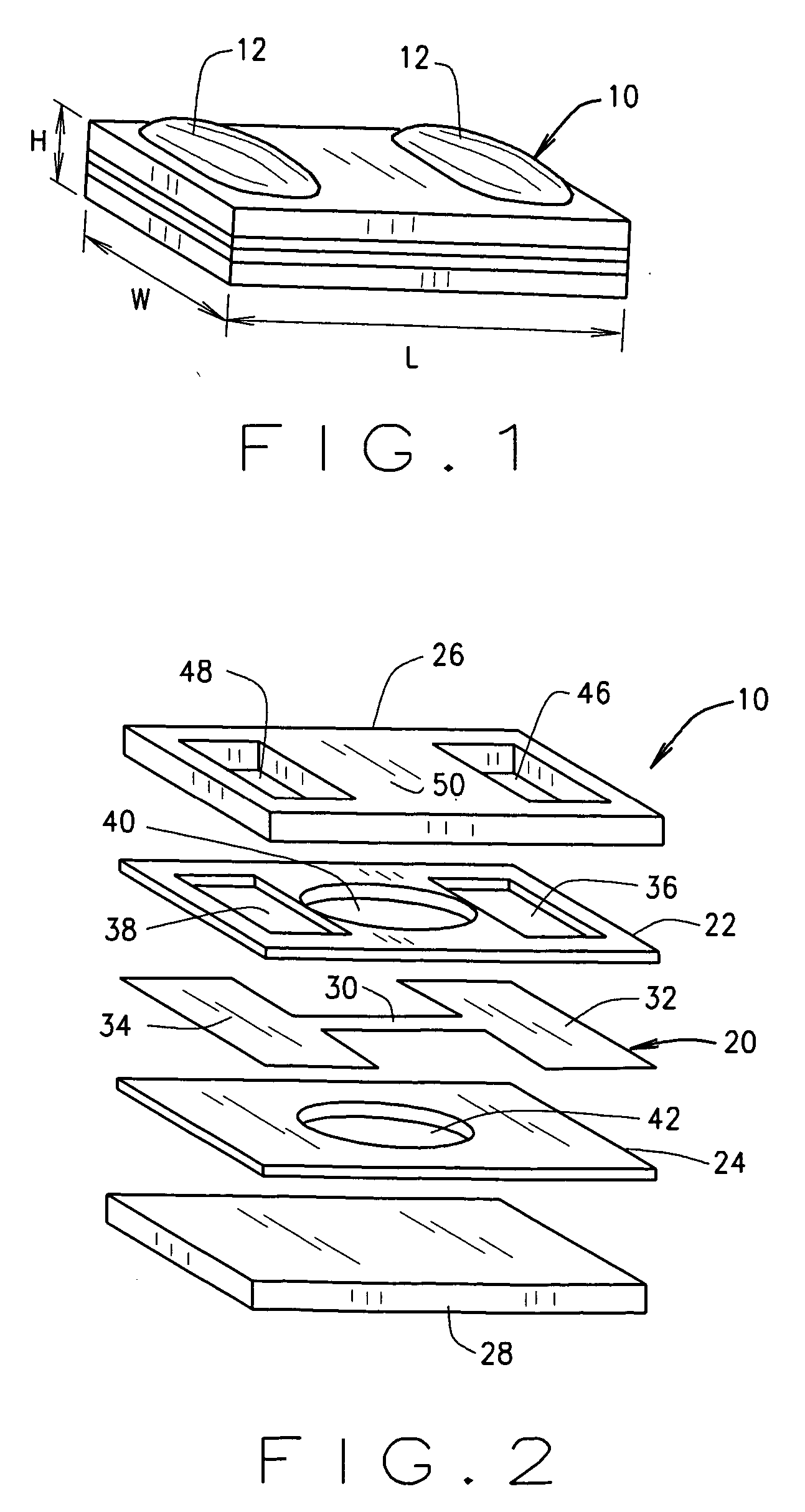
[0069]FIG. 4 is an exploded perspective view of a foil fuse 90 substantially similar to fuse 10 (described above in relation to FIGS. 1-3) except for the construction of lower intermediate insulating layer 24. Notably, fusible link opening 42 (shown in FIG. 2) in lower intermediate insulating layer 24 is not present in fuse 90, and fusible link 30 extends directly across the surface of lower intermediate insulation layer 24. This particular construction is satisfactory for fuse operation at intermediate temperatures in that fusible link opening 40 will inhibit or at least reduce heat transfer from fusible link 30 to intermediate insulating layers 22, 24. Resistance of fuse 90 is accordingly reduced during fuse operation, and fusible link opening 40 in upper intermediate insulating layer 40 inhibits arc tracking and facilitates full clearing of the circuit through the fuse.

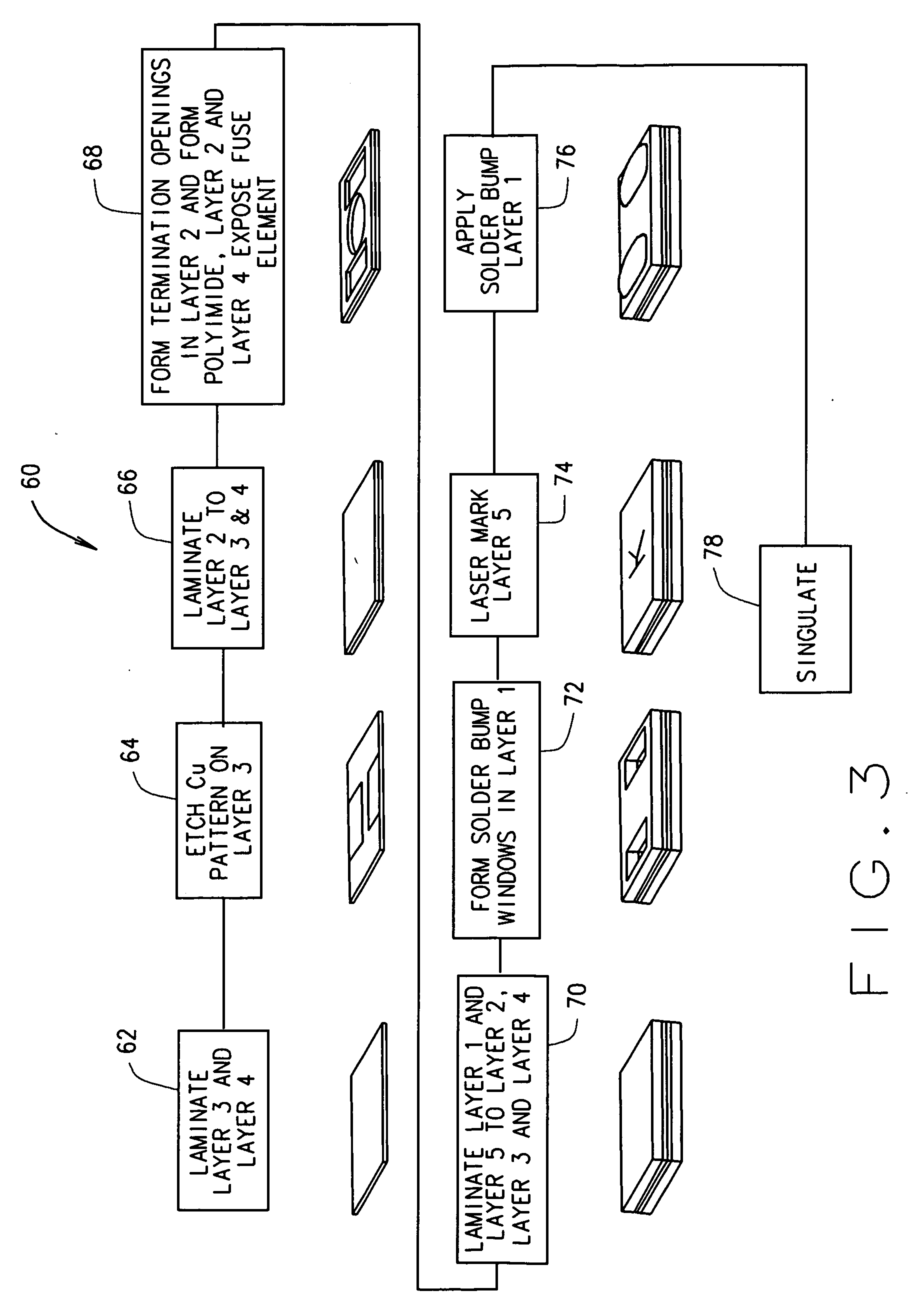
[0070] Fuse 90 is constructed in substantial accordance with method 60 (described above in relation to FIG. 3) e...

third embodiment

[0071]FIG. 5 is an exploded perspective view of a foil fuse 100 substantially similar to fuse 90 (described above in relation to FIG. 4) except for the construction of upper intermediate insulating layer 22. Notably, fusible link opening 40 (shown in FIG. 2) in upper intermediate insulating layer 22 is not present in fuse 100, and fusible link 30 extends directly across the surface of both upper and lower intermediate insulation layers 22, 24.

[0072] Fuse 100 is constructed in substantial accordance with method 60 (described above in relation to FIG. 3) except, of course, that fusible link openings 40 and 42 (shown in FIG. 2) in intermediate insulating layers 22, 24 are not formed.

[0073] It is appreciated that thin ceramic substrates may be employed in any of the foregoing embodiments in lieu of polymer films, but may be especially advisable with fuse 100 to ensure proper operation of the fuse. For example, low temperature cofireable ceramic materials and the like may be employed in...

fourth embodiment

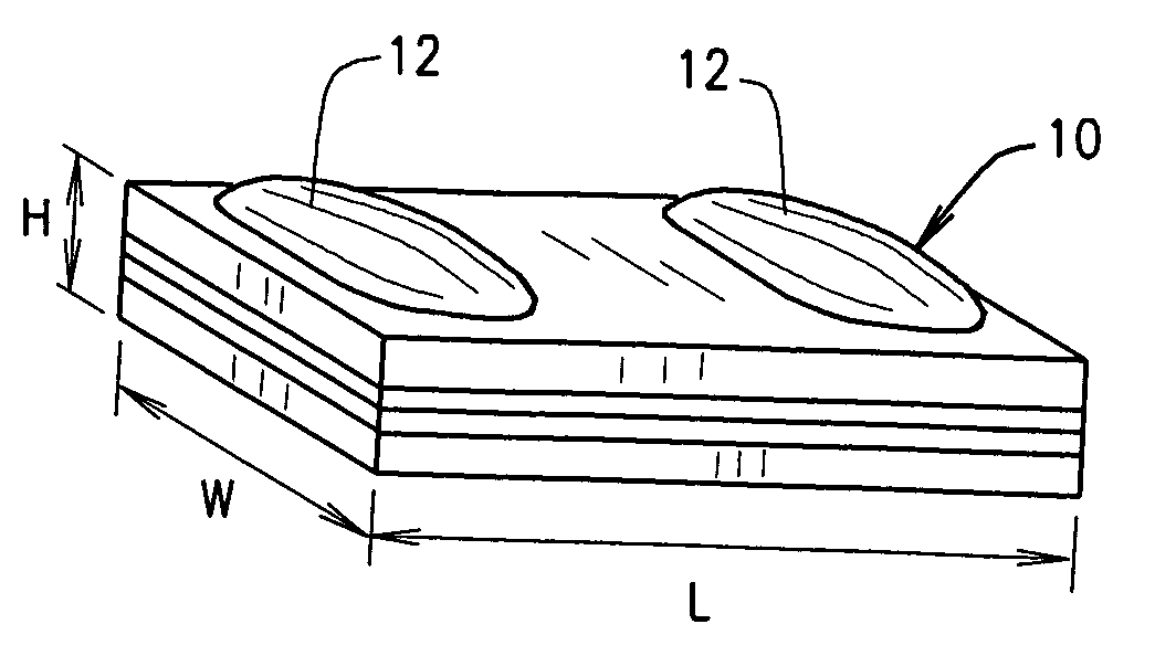
[0075]FIG. 11 is an exploded perspective view of a fuse 120. Like the fuses described above, fuse 120 provides a low resistance fuse of a layered construction that is illustrated in FIG. 11. Specifically, in an exemplary embodiment, fuse 120 is constructed essentially from five layers including foil fuse element layer 20 sandwiched between upper and lower intermediate insulating layers 22, 24 which, in turn, are sandwiched between upper and lower outer insulation layers 122, 124.

[0076] In accord with the foregoing embodiments fuse element 20 is an electro deposited, 3-20 micron thick copper foil applied to lower intermediate layer 24 according to known techniques. Thin fuse element layer 20 is formed in the shape of a capital I with a narrowed fusible link 30 extending between rectangular contact pads 32, 34, and is dimensioned to open when current flowing through fusible link 30 is less than about 20 ampere. It is contemplated, however, that various dimensions of the fusible link m...


PUM

PropertyMeasurementUnit
Electrical resistanceaaaaaaaaaa
Fusibilityaaaaaaaaaa
aaaaaaaaaa

Abstract

A low resistance fuse apparatus and methods of manufacture includes a first intermediate insulation layer, a second intermediate insulation layer, and a free standing fuse element layer independently formed and fabricated from each of the first and second intermediate insulation layers, The fuse element layer includes first and second contact pads and a fusible link extending therebetween. The first and second intermediate insulation layers extend on opposite sides of the free standing fuse element layer and are laminated together with the fuse element layer therebetween.

Description

CROSS REFERENCE TO RELATED APPLICATIONS [0001] This application is a continuation-in-part application of U.S. application Ser. No. 10 / 767,027 filed Jan. 29, 2004, which is a continuation-in-part of U.S. application Ser. No. 10 / 339,114 filed Jan. 9, 2003, which claims the benefit of Provisional Application Ser. No. 60 / 348,098 filed Jan. 10, 2002.BACKGROUND OF THE INVENTION [0002] This invention relates generally to fuses, and, more particularly, to fuses employing foil fuse elements. [0003] Fuses are widely used as overcurrent protection devices to prevent costly damage to electrical circuits. Typically, fuse terminals or contacts form an electrical connection between an electrical power source and an electrical component or a combination of components arranged in an electrical circuit. One or more fusible links or elements, or a fuse element assembly, is connected between the fuse terminals or contacts, so that when electrical current through the fuse exceeds a predetermined thresho...

Claims


Application Information

Patent Timeline
IPC IPC(8): H01H69/02H01H85/00H01H85/046
CPCH01H69/022H01H85/0047H01H85/006Y10T29/49107H01H85/046H01H2085/0414H01H85/0411H01H85/044H01H85/10H01H85/11H01H85/18H01L23/3672H01L23/473H01L23/467
Inventor BENDER, JOAN LESLIEKAMATH, HUNDI PANDURANGAKALRA, VARINDER KUMARMANOUKIAN, DANIEL MINASSO, PETER YORK
Owner EATON INTELLIGENT POWER LIMITED
Why Eureka
Try Eureka