
Surface light source device and liquid crystal display device

a light source device and liquid crystal display technology, applied in the direction of identification means, lighting and heating apparatus, instruments, etc., can solve the problems of light leakage through the slits, difficulty in increasing strength,

Active Publication Date: 2005-06-30
SHARP KK
View PDF2 Cites 20 Cited by
  • Summary
  • Abstract
  • Description
  • Claims
  • Application Information

AI Technical Summary

Benefits of technology

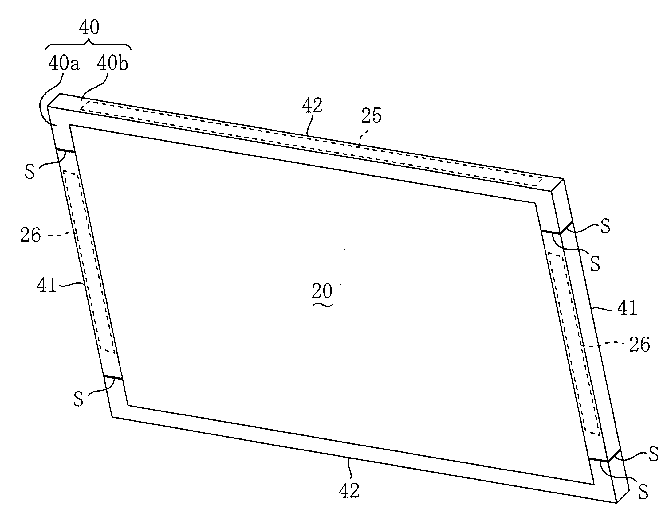
[0009] The present invention has been made in view of the above matter and has its main object of preventing, in a surface light source device such as a liquid crystal display device in which a frame composed of a plurality of divisional members connected is arranged along the peripheral portion of a light emitting face of a backlight section as a light source section arranged at the back side of a liquid crystal display panel as an optical panel, light of the light source section from leaking through slits between the divisional members in the front face portion of the frame.
[0010] To attain the above object, in the present invention, the frame having a front face portion arranged so as to cover the peripheral portion of the light emitting face of the light source section and a side face portion extending from the outer periphery of the front face portion toward the light source section is composed of the divisional members connected with each other, and a light shielding portion is provided at each slit between the divisional members in the front face portion of the frame, whereby the light shielding portion prevents light of the light source section from leaking through each slit.
[0012] At each slit between the divisional members in the front face portion of the frame, a light shielding portion for preventing light of the light source section from leaking through the slit is provided.
[0014] Moreover, it is preferable that the divisional members are connected by welding and each welded portion formed by the welding serves as the light shielding portion. Further, in the welding, if at least part of each slit between the divisional members in the side face portion is welded in addition to the welding of each slit between the divisional members in the front face portion, the torsional strength of the frame is increased in combination with the welding of the front face portion.

Problems solved by technology

Therefore, it is difficult to increase the strength by widening the rim portion of the bezel.
However, in the above conventional cases, small slits are liable to be formed at the connected portions between the divisional members in the front face portion of the frame, and light of the light source section leaks through the slits.

Method used


Image

  • Surface light source device and liquid crystal display device
  • Surface light source device and liquid crystal display device
  • Surface light source device and liquid crystal display device

Examples


Embodiment Construction

[0025] An embodiment of the present invention will be described below with reference to drawings.

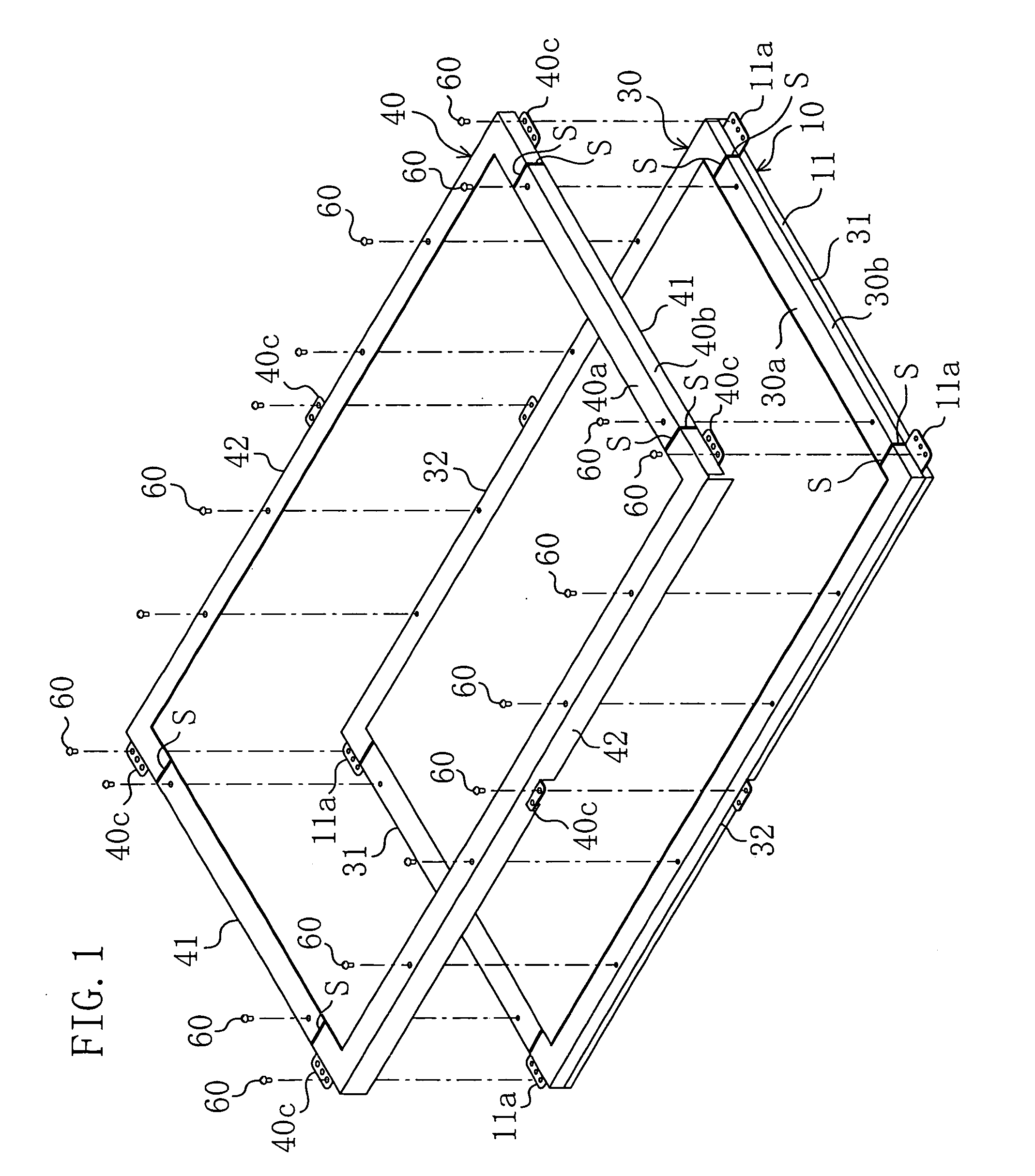
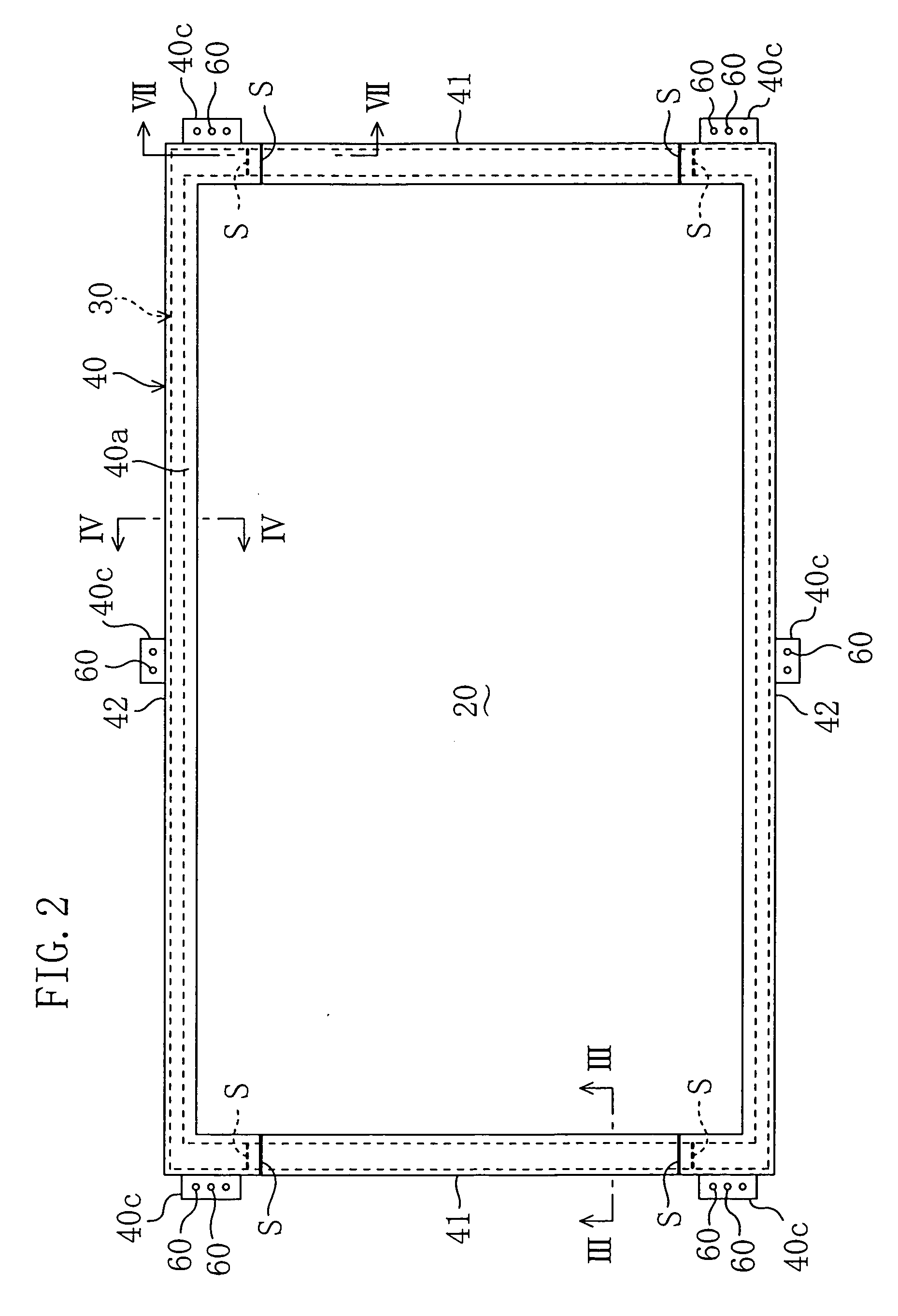
[0026]FIG. 1 of an exploded perspective view and FIG. 2 of a plan view show schematically the whole construction of a liquid crystal display device according to the embodiment of the present invention, wherein the liquid crystal display device is used as a display device for a 37-inch wide liquid crystal television set of which height to width ratio of the display screen is 9:16.

[0027] As shown in FIG. 3, which is an enlarged section taken along the line III-III in FIG. 2, and FIG. 4, which is an enlarged section taken along the line IV-IV in FIG. 2, the liquid crystal display device includes: a backlight section 10 as a light source section having a rectangular light emitting face 10a; a liquid crystal display panel 20 as an optical panel arranged so as to cover the light emitting face 10a of the backlight section 10; a mounting frame 30 as a rear frame for fixing the liquid crystal d...


PUM


Abstract

In a surface light source device including: a light source section having a light emitting face; an optical panel arranged so as to cover the light emitting face; and a at least one frame having a front face portion that covers the peripheral portion of the light emitting face, the at least one frame is composed of a plurality of divisional members connected with each other and a light shielding portion is provided at each slit between the divisional members in the front face portion of the at least one frame. Whereby, light from the light source section is prevented from leaking through each slit between the divisional members in the front face portion of the at least one frame.

Description

CROSS REFERENCE TO RELATED APPLICATIONS [0001] This Non-provisional application claims priority under 35 U.S.C. § 119(a) on Patent Application No. 2003-318683 filed in Japan on Sep. 10, 2003, and No. 2004-239881 filed in Japan on Aug. 19, 2004, the entire contents of which are hereby incorporated by reference.BACKGROUND ART [0002] The present invention relates to a surface light source device in which a frame is arranged along the peripheral portion of a light emitting face of a light source section, such as a liquid crystal display device including a backlight section as a light source section at a back face of a liquid crystal display panel, and particularly relates to improvement in the frame thereof. [0003] In general, in a liquid crystal display device including a backlight section at the back face of a liquid crystal display panel, the liquid crystal display panel is mounted at a frame of the backlight section and a bezel (rim) is arranged on the peripheral portion of the liqu...

Claims


Application Information

Patent Timeline
IPC IPC(8): G02F1/1333F21S2/00G02F1/13G02F1/13357G09F9/00
CPCG02F1/133308G02F2001/133328G02F1/133608G02F1/133328
Inventor SUGAHARA, TATSUOHARA, TAKAFUMIUEDA, FUJIOKUDARI, TATSUYA
Owner SHARP KK
Learn More