Optical pickup

a technology of optical pickups and pickups, applied in the field of optical pickups, can solve the problems of increasing costs, inability to control the position and/or rotation, and ineffective optimum conditions, and achieve the effect of reducing integration and easy assembly control

Inactive Publication Date: 2005-06-30
SHARP KK
View PDF62 Cites 17 Cited by
  • Summary
  • Abstract
  • Description
  • Claims
  • Application Information

AI Technical Summary

Benefits of technology

[0024] It is an object of the present invention to provide an optical pickup which is compatible with a plurality of optical disks of different specs for performing recording and reproducing using light beams of different wavelengths, capable of an easy assembly control, and suitable for downsizing integration.
[0028] As explained, the reflecting light including light beams of different wavelengths from the optical disk is split into different optical paths by the optical path splitting element, and the thus split light beams are diffracted at the first and second hologram elements, respectively, thereby guiding the light beams to the shared photosensor. This enables the shared use of the photosensor between the light beams having different wavelengths regardless of the positions of the first and second light sources. Consequently, it is possible to provide an optical pickup which is capable of performing recording or reproducing with respect to the plurality of optical disks having different specs which are recorded and played back by using light beams of different wavelengths, and further being suitable for integrating lasers and light receiving elements into a single package.
[0030] With this arrangement, when, for example, the optical path splitting element transmits one of the reflecting light beams while reflecting the other, it is possible to correct deviation in the latter reflecting light beam caused by the optical path splitting element by the following control: the hologram elements are first controlled so as to control the position of the former reflecting light beam over the photosensor, then, the hologram elements are fixed, thereafter controlling the optical path splitting element so as to make the foregoing correction of deviation. Consequently, the hologram elements and / or the PBS can be controlled independently with respect to the respective light sources, thereby easily performing optimum assembly control with respect to light from the all light sources. This realizes milder tolerances in the mounting of the lasers and the light receiving elements and in the packaging process, thereby greatly reducing costs.

Problems solved by technology

Therefore, it is often the case that the control of a position and / or rotation is not available for the light receiving element when controlling the hologram element.
However, in that case, when optimizing the hologram element for one of semiconductor laser light sources, it is very likely that the same optimum condition becomes ineffectual when using the hologram element with another semiconductor laser light source.
More specifically, controlling only the position of the hologram element in the assembly raises problems such that servo error signals cannot be optimized, or tolerances in the mounting of the laser and the light receiving element, in packaging, and the like are made highly exacting, thereby increasing costs.
Further, the hologram element is often provided with an aberration correction function so as to obtain desirable light converging characteristics on the light receiving element; however, it is difficult to design such a hologram pattern as to perform optimum aberration correction with respect to a plurality of different wavelengths.
Furthermore, the conventional optical pickup has a problem that it is not applicable to a plurality of optical disks of different specs in which different tracking error signals are used, respectively, because only a tracking error signal according to the three-beam method can be detected from either of light beams of the semiconductor laser having a plurality of waveforms.

Method used


Image

  • Optical pickup
  • Optical pickup
  • Optical pickup

Examples


first embodiment

[0070] The following will explain in detail the present invention with reference to FIGS. 1 through 20. Note that, components identical with those shown in the conventional example above will be given the same reference symbols, and explanation thereof will be omitted here.

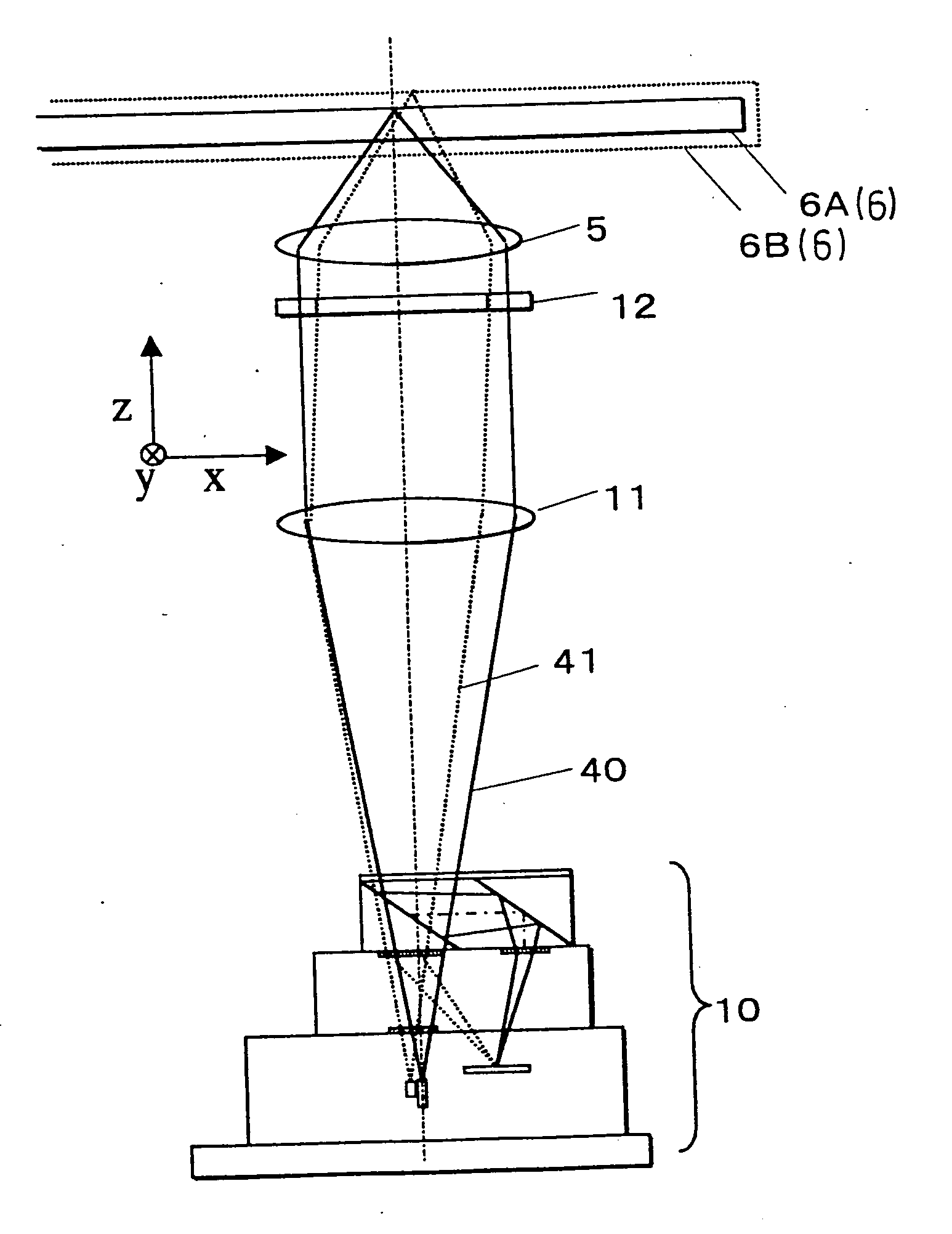
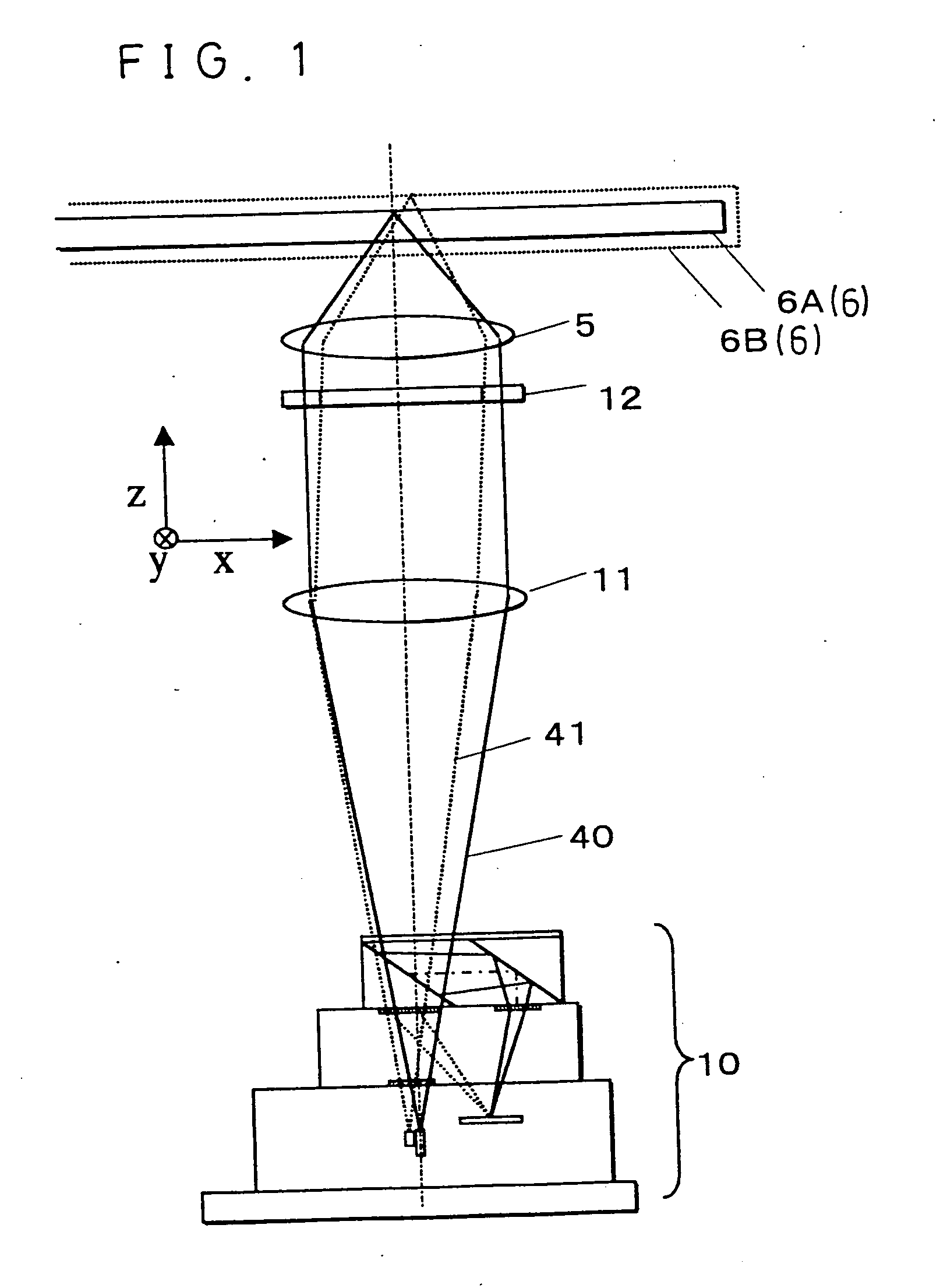
[0071]FIGS. 1 and 2 are schematic diagrams of an optical pickup according to the present embodiment. Light emitted from an integrated laser unit 10 is changed into parallel light at a collimator lens 11 and transmitted through a wavelength selecting aperture 12, thereafter being focused on an optical disk 6 by an objective lens 5. The reflection light from the optical disk 6 travels through same optical components as those of an outward travel so as to be focused on a photosensor 27 of the integrated laser unit 10.

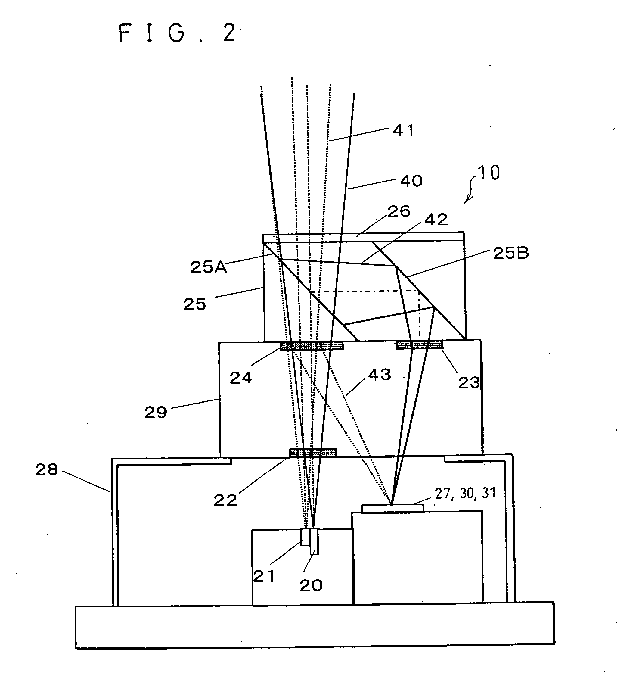
[0072] Details of the integrated laser unit 10 will be discussed with reference to FIG. 2. The integrated laser unit 10 includes a first semiconductor laser 20 which starts oscillating when a wavelength...

second embodiment

[0209] Next, the following will explain details of another configuration according to the present invention, with reference to FIG. 23. Note that, the same portions as those of the above configuration of FIG. 21 will be given the same reference symbols, and explanation thereof will be omitted here.

[0210] In the integrated laser unit 10 of FIGS. 21 and 22, in the case of controlling the first and second hologram elements 23 and 24, the complex PBS 25 and the first hologram element 23 on the upper side are first controlled integrally. Thereafter, the second hologram element 24 on the lower side should be controlled while fixing the complex PBS 25 and the first hologram element 23 thus integrally controlled lest they should move. However, such control poses problems in terms of fabrication that devices such as controlling tools become complicated, and stricter accuracy is demanded. Therefore, a configuration to solve these problems will be described below.

[0211]FIG. 23 shows an integr...


PUM

PropertyMeasurementUnit
wavelengthaaaaaaaaaa

Abstract

An optical pickup can be provided, the optical pickup being capable of recording and playback of a plurality of optical disks having different specs by using light beams of different wavelengths, and further being suitable for integrating the semiconductor lasers and light receiving elements into a single package, by including: first and second semiconductor lasers adjacently disposed; a three-beam diffraction grating for generating three beams for tracking control; a second hologram element for diffracting light of the second semiconductor laser to guide it to a photosensor; a complex polarization beam splitter (PBS) for reflecting only light from the first semiconductor laser; and a first hologram element for diffracting light of the first semiconductor laser to guide it to the photosensor.

Description

FIELD OF THE INVENTION [0001] The present invention relates to an optical pickup which performs optical recording and reproducing of information with respect to information recording media such as an optical disk and an optical card, and in particular to a compatible optical pickup applicable to a plurality of optical disks of different specifications for performing recording and reproducing using light beams having different wavelengths. BACKGROUND OF THE INVENTION [0002] In recent years, an optical disk has been utilized in a variety of fields of audios, videos, computers and the like, because of its capability of recording a large quantity of information signals with high density. [0003] Particularly, optical disks having various different specifications (specs) such as CDs, CD-Rs and DVDs have been commercially available. What is required of an optical pickup is compatibility with these disks of the different specs so that a single optical pickup can perform recording or reprodu...

Claims


Application Information

Patent Timeline
Patent Type & Authority Applications(United States)
IPC IPC(8): G11B7/00G11B7/09G11B7/12G11B7/125G11B7/13G11B7/135G11B7/22
CPCG11B7/0901G11B7/0903G11B7/0906G11B7/0908G11B7/0916G11B7/1205G11B2007/0006G11B7/131G11B7/1353G11B7/1356G11B7/1365G11B7/1381G11B7/22G11B7/1275G11B7/123G11B7/1395
Inventor UEYAMA, TETSUOSAKAI, KEIJIKURATA, YUKIOMASUI, KATSUSHIGEOTSUKA, NAOTAKAMIKI, RENZABUROHIRAJIMA, HIROSHIGEFUJITA, NOBORU
Owner SHARP KK
Why Eureka
Try Eureka