Automatic power-off control circuit for essential oil burner

a technology of power-off control circuit and essential oil burner, which is applied in the direction of disease, life-saving devices, horticulture, etc., can solve problems such as safety hazards, and achieve the effect of improving operational convenience and improving the safety of essential oil burner us

Inactive Publication Date: 2005-06-30
LEE CHAU YOUNG +1
View PDF7 Cites 3 Cited by
  • Summary
  • Abstract
  • Description
  • Claims
  • Application Information

AI Technical Summary

Benefits of technology

[0007] Because of the shortcomings in the conventional designs, the first object of the present invention is to provide an essential oil burner with an automatic power-off control circuit. With the automatic power-off control circuit, the safety and the convenience of using essential oil burners can be improved.
[0009] Yet another object of the present invention is to provide an automatic power-off control circuit with a self-holding circuit for an essential oil burner. When the users press the power-on switch to activate the essential oil burner, the control circuit can keep supplying power to the heating device of the essential oil burner in a self-holding manner. This improves the operational simplicity.
[0012] Through the technologies adopted in the present invention, the essential oil burner can detect that the essential oil in the burner is used up and automatically cut off the power when it is in use. This greatly improves the safety of essential oil burner usage. Furthermore, the self-holding circuit of the control circuit of the present invention allows the user only need to press the power-on switch to activate the essential oil burner. The self-holding feature of the control circuit can keep the power supplied to the heating device. This improves the operational convenience.

Problems solved by technology

For example, it is a safety hazard if the user forgets to turns off the power when the essential oil in the essential oil burner is used up.

Method used


Image

  • Automatic power-off control circuit for essential oil burner
  • Automatic power-off control circuit for essential oil burner
  • Automatic power-off control circuit for essential oil burner

Examples


Embodiment Construction

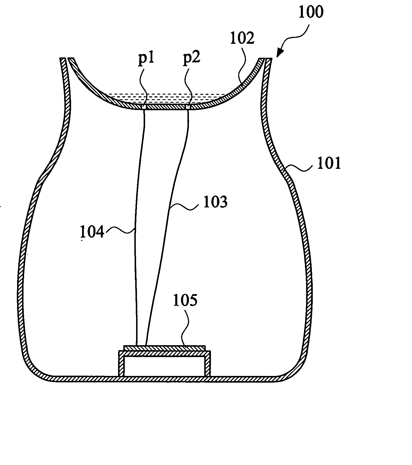
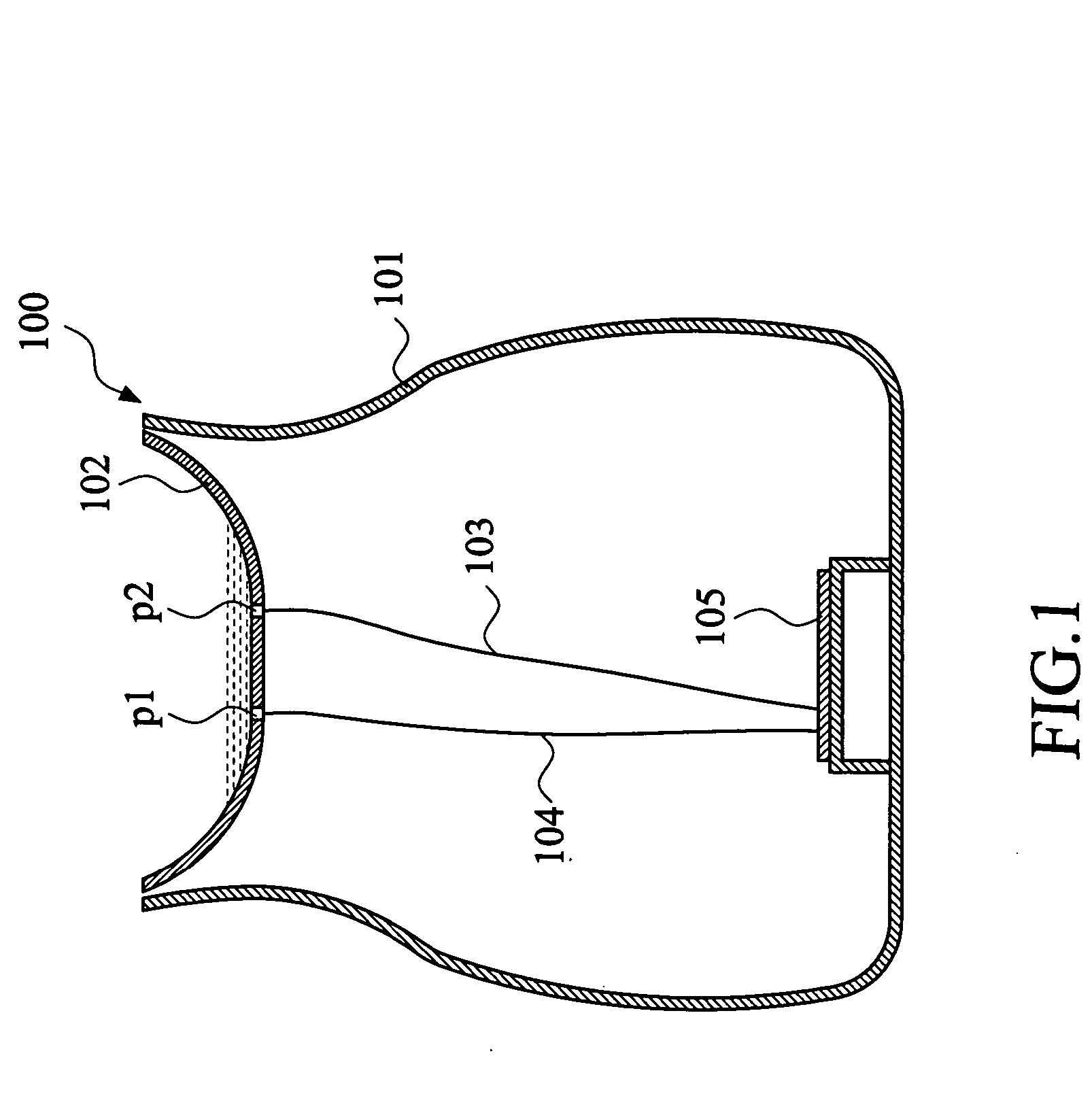
[0017]FIG. 1 shows a schematic side view of the present invention of an essential oil burner with an automatic power-off control circuit. An essential oil burner 100 includes a main body 101 and an essential oil bowl 102 for placing essential oil of an appropriate quantity. The essential oil bowl 102 includes a pair of detection electrodes p1, p2 at appropriate locations for detecting the presence of essential oil in essential oil bowl 102. The signal indicating the presence of the essential oil detected by detection electrodes p1, p2 is transmitted through a pair of signal lines 103, 104 to a circuit board 105, which is appropriately located inside main body 101 of essential oil burner 100.

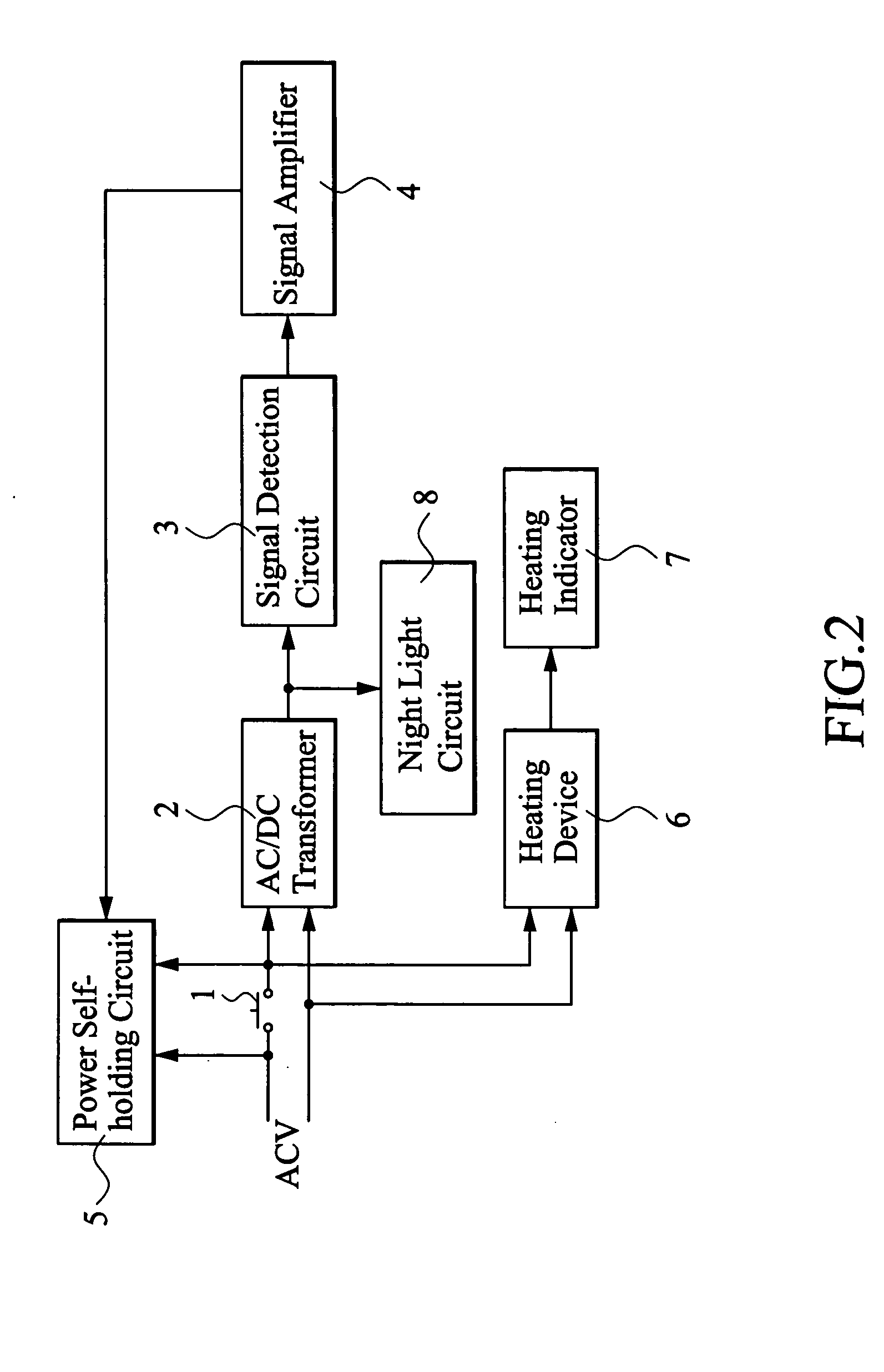
[0018]FIG. 2 shows a functional block diagram of the control circuit of the present invention. The block diagram includes a power-on switch 1, an AC / DC transformer 2, a signal detection circuit 3, a signal amplifier 4, a power self-holding circuit 5, a heating device 6, a heating indicator 7, an...


PUM

PropertyMeasurementUnit
AC poweraaaaaaaaaa
DC voltageaaaaaaaaaa
air-permeableaaaaaaaaaa

Abstract

An automatic power-off control circuit of essential oil burner is provided for controlling the heating of the essential oil in the essential oil burner, and cutting off power when the essential oil in the essential oil burner is used up. The control circuit includes a power-on switch, an AC / DC transformer, a signal detection circuit, a signal amplifier, and a heating device. The power-on switch is connected in series between an AC power supply and the AC / DC transformer. The power-on switch is connected in parallel with a power self-holding circuit so that the AC power supply keeps supplying power to the heating device to heat the essential oil in the bowl when the switch is pressed and the signal detection circuit detects the presence of essential oil in the bowl of the essential oil burner. When the signal detection circuit detects that essential oil is used up in the bowl, the self-holding circuit relieves its self-holding state and cuts off the supplying of the power to the heating device. The control circuit further includes a heating indicator and a night light circuit.

Description

BACKGROUND OF THE INVENTION [0001] 1. Field of the Invention [0002] This invention relates to a control circuit for essential oil burner and, more particularly, to an automatic power-off control circuit for essential oil burner. [0003] 2. Description of the Prior Art [0004] As more and more people are concerned with improving the quality of life in the recent years, many novel equipments and facilities are manufactured to meet the growing need for those seeking quality lifestyle. The essential oil burner is one of the items that have gained much popularity due to its ease of use and reputable effects. [0005] Conventional essential oil burners provide different designs to meet different purposes. For example, Taiwan patent publication No. 437,917 disclosed a design of essential oil burner whose burning base is placed on a container with a heating wick in the middle. The other end of the heating wick is soaked in the essential oil in the container. The burning base can be covered with...

Claims


Application Information

Patent Timeline
Patent Type & Authority Applications(United States)
IPC IPC(8): A61L9/013A61L9/03
CPCA61L9/03A61L9/013
Inventor LEE, CHAU-YOUNGCHEN, HSU-CHANG
Owner LEE CHAU YOUNG
Why Eureka
Try Eureka