
Arthroplasty devices configured to reduce shear stress

a technology of arthroplasty and stress reduction, applied in the field of arthroplasty devices, can solve the problems of compromising fixation, abnormal stress transference from the implant to the bone, and the patient's implant with respect to the bone, and achieve the effect of improving bone ingrowth ability

Inactive Publication Date: 2005-06-30
FERREE BRET A
View PDF26 Cites 70 Cited by
  • Summary
  • Abstract
  • Description
  • Claims
  • Application Information

AI Technical Summary

Benefits of technology

[0009] It is, therefore, an object of the present invention to provide an arthroplasty device which has improved bone ingrowth capabilities.
[0010] It is a further object of the present invention to provide an arthroplasty device configured to reduce shear stress.
[0011] It is a still further object of the present invention to provide an arthroplasty device having a resorbable component which restricts motion in a joint for a period of time to allow for improved bone ingrowth.

Problems solved by technology

One problem encountered with prosthetic joints includes movement of the implant with respect to the patient's bones.
This motion often compromises fixation.
Another problem that occurs is an abnormal stress transference from the implant to the bone.
This often causes abnormal stress distribution, leading to premature failure.
The difficulty of achieving true growth of a patient's bone into a metal prosthesis is a well known problem in the surgical field.

Method used


Image

  • Arthroplasty devices configured to reduce shear stress
  • Arthroplasty devices configured to reduce shear stress
  • Arthroplasty devices configured to reduce shear stress

Examples


Embodiment Construction

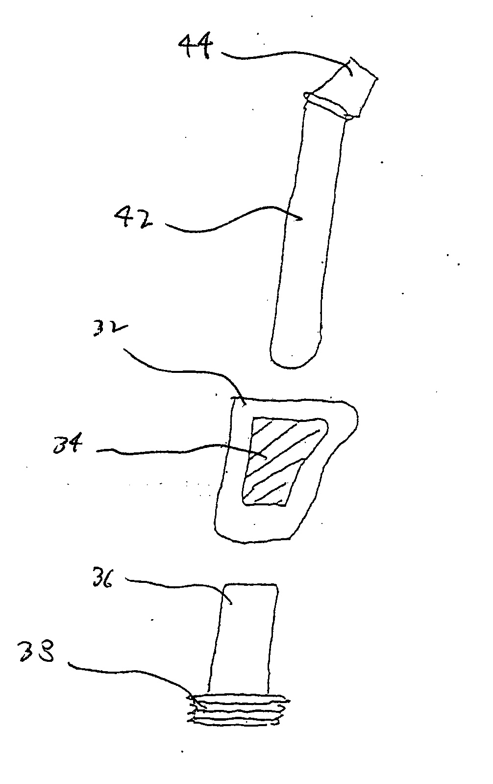
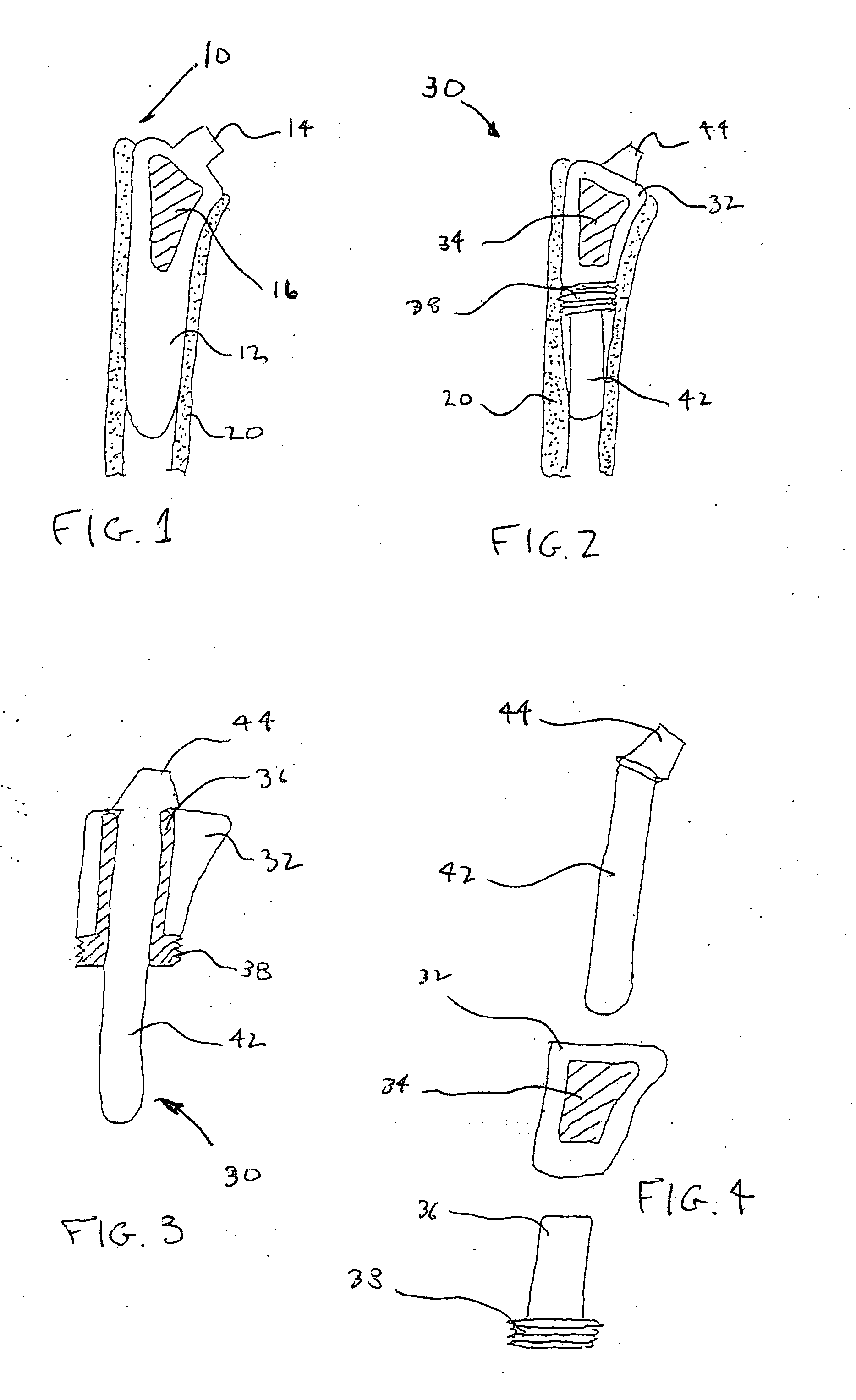
[0076]FIG. 1. represents a typical prior art impacted femoral component of a hip replacement commonly used in the surgical field today. Referring now to FIG. 1, there is shown a femoral component 10 having an elongated tapered portion 12, an extended stem portion 14 for connecting component 10 to the prosthetic femoral head, and a textured surface area 16. In use, tapered portion 12 is driven into a femur 20 which has been prepared to receive component 10. Surface area 16 of component 10 is configured to encourage bone ingrowth to assist in the permanent attachment of component 10 within femur 20. Surface area 16 may contain small beads, fibrillar wires or other structures known in the art to promote bone ingrowth. This type of arthroplasty device relies on impaction of the device into patients' bones for stability.

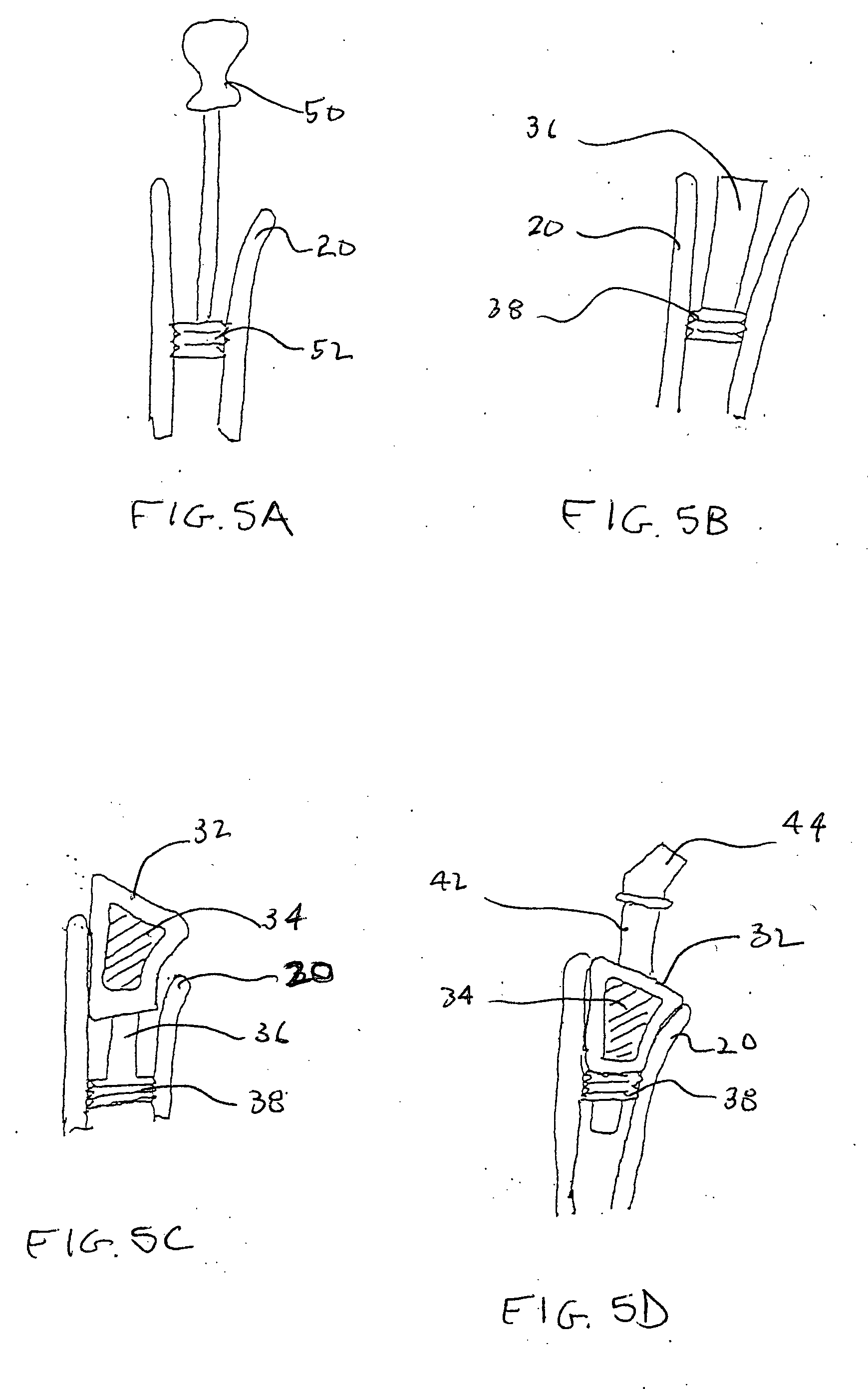
[0077] The difficulty of achieving true growth of a patient's bone into metal prostheses is well known in the medical field. FIGS. 2-4 show a device according to the pre...


PUM

PropertyMeasurementUnit
Shapeaaaaaaaaaa
Shear stressaaaaaaaaaa

Abstract

Arthroplasty devices having improved bone in growth to provide a more secure connection within the body. Different embodiments disclosed include devices having threaded intramedullary components, devices configured to receive bone growth promoting substances, devices with resorbable components, and devices configured to reduce shear stress.

Description

[0001] This application is a continuation in part of U.S. patent application Ser. No. 10 / 608,616, filed Jun. 27, 2003, which application claims benefit from U.S. Provisional Patent Application Ser. No. 60 / 392,234, filed Jun. 27, 2002, which applications are incorporated herein by reference.BACKGROUND OF THE INVENTION [0002] 1. Field of the Invention [0003] The present invention is directed in general to arthroplasty devices and, in particular, to arthroplasty devices which improve bone growth into said devices. [0004] 2. Description of the Related Art [0005] The use of arthroplasty devices to replace damaged or defective joints within the body is commonplace in the medical field. The prosthetic replacement of joints has evolved over the years from early relatively crude models to current prostheses which closely replicate functions and motions of a natural joint. Prosthetic arthroplasty devices have been used as replacements for the shoulder, hips, knee, ankle and invertebral disc. ...

Claims


Application Information

Patent Timeline
IPC IPC(8): A61B17/16A61B17/74A61B17/78A61B17/86A61B19/00A61F2/00A61F2/02A61F2/28A61F2/30A61F2/32A61F2/34A61F2/36A61F2/38A61F2/44A61F2/46
CPCA61B17/164A61B17/1655A61B17/1668A61B17/1671A61B17/1675A61B17/1684A61B17/744A61B17/86A61B2019/306A61F2/30723A61F2/30724A61F2/30734A61F2/30767A61F2/30771A61F2/32A61F2/34A61F2/36A61F2/3662A61F2/367A61F2/3676A61F2/389A61F2/442A61F2/4425A61F2/447A61F2/4601A61F2/4607A61F2002/2817A61F2002/30004A61F2002/30034A61F2002/30062A61F2002/30112A61F2002/30123A61F2002/30154A61F2002/30158A61F2002/30205A61F2002/30224A61F2002/30233A61F2002/30235A61F2002/30261A61F2002/30289A61F2002/30354A61F2002/30365A61F2002/30367A61F2002/30377A61F2002/30433A61F2002/30434A61F2002/30474A61F2002/30507A61F2002/30545A61F2002/3055A61F2002/30556A61F2002/30579A61F2002/30604A61F2002/30626A61F2002/30733A61F2002/30738A61F2002/30784A61F2002/30787A61F2002/30789A61F2002/30794A61F2002/30795A61F2002/30797A61F2002/30827A61F2002/3085A61F2002/30884A61F2002/30909A61F2002/30975A61F2002/3401A61F2002/3469A61F2002/3611A61F2002/3625A61F2002/3631A61F2002/365A61F2002/368A61F2002/3694A61F2002/4602A61F2002/4631A61F2002/4638A61F2210/0004A61F2220/0025A61F2220/0033A61F2220/0041A61F2230/0004A61F2230/0006A61F2230/0021A61F2230/0026A61F2230/0067A61F2230/0069A61F2230/0082A61F2230/0091A61F2250/0009A61F2250/001A61F2250/0014A61F2250/0031A61F2310/00023A61F2310/00029A61F2310/00059A61F2310/00293A61F2310/00365A61F2310/00976A61F2310/00982A61B2090/036A61F2002/30032A61F2002/30624A61F2002/3079
Inventor FERREE, BRET A.
Owner FERREE BRET A
Learn More