
Processing system

Inactive Publication Date: 2005-06-30
FANUC LTD
View PDF10 Cites 23 Cited by
  • Summary
  • Abstract
  • Description
  • Claims
  • Application Information

AI Technical Summary

Benefits of technology

[0007] Accordingly, an object of the present invention is to provide a processing system for stably processing the workpiece even if the shape of the workpiece changes every production lot of the workpiece, or by a change in the workpiece.

Problems solved by technology

In such a case, the suitable distance of the gap between a nozzle of a laser machining head and a workpiece required for laser machining cannot be obtained and, therefore, laser machining cannot be suitably implemented.
When the difference is large, acceleration and deceleration of the laser machining head may be delayed and may not fully perform the motion for correcting the difference and, therefore, the laser machining head may interfere with the workpiece.
Therefore, even if the distance of the gap between the nozzle of the laser machining head and the workpiece by the distance sensor and machining is implemented by the feedback control for suitably correcting the gap, when the distance to be corrected is relatively large, the motion of the laser machining head may be insufficient for correcting the distance and the laser machining head may interfere with the workpiece.

Method used


Image

  • Processing system
  • Processing system
  • Processing system

Examples


Embodiment Construction

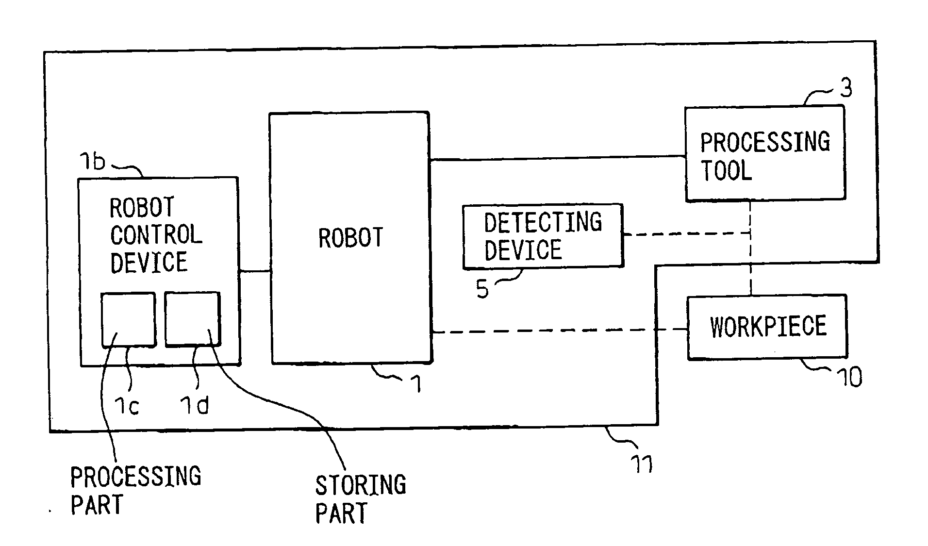
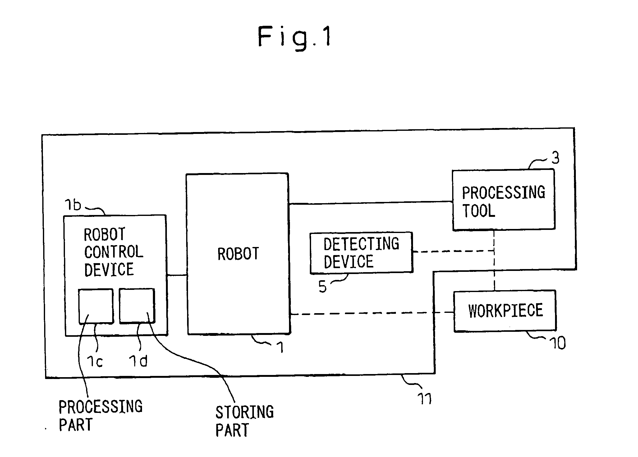
[0026] As shown in FIG. 1, the processing system 11 according to the present invention has a robot 1 configured such that a processing tool 3 for processing a workpiece 10 is movably held by the robot 1 relative to the workpiece 10. Alternatively, the robot 1 may be configured to movably hold the workpiece 10 relative to the fixed processing tool 3. The processing system 11 also has a detecting device 5 for sensing the distance between the workpiece 10 and the processing tool 3, and a robot control device 1b for controlling the robot 1. The robot control device 1b has a storing part 1d for storing a processing program including teaching points forming a processing path of the workpiece 10, and a processing part 1c for feedback controlling the distance between the workpiece 10 and the processing tool 3, sensed by the detecting device 5 during processing, by executing the processing program stored in the storing part 1d. The processing part 1c controls the robot 1 such that the proces...


PUM


Abstract

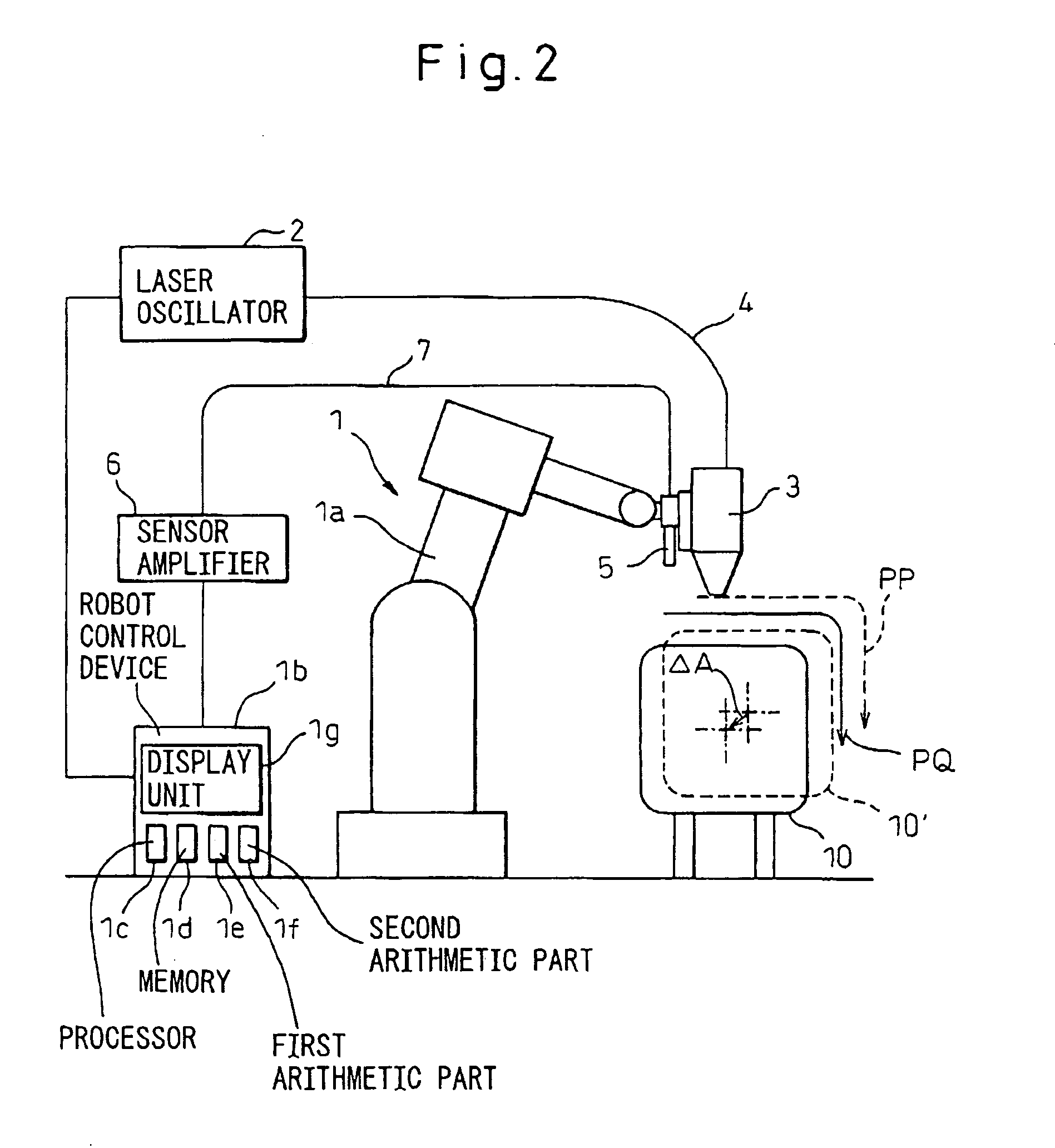
A processing system for stably processing a workpiece even if the shape of the workpiece changes every production lot of the workpiece, or by a change of the workpiece. The distance between the workpiece and an end of a nozzle of a laser machining head is measured by a distance sensor. A data correcting value ΔZ′mn is calculated using a measured distance ΔZrn at each teaching point and a set gap value ΔZs (step S6-S15). By using ΔZ′mn, the data of the teaching points are corrected to new data of the teaching points of the program (step S16-S19). The distance between the workpiece and the end of the nozzle of the laser machining head does not become larger because the teaching points of the processing program are corrected every time when the workpiece is processed. The interference between the workpiece and the head may be prevented and the processing may be stably implemented because the amount of correction becomes smaller when the position of the head is corrected during the processing.

Description

BACKGROUND OF THE INVENTION [0001] 1. Field of the Invention [0002] The present invention relates to a processing system for processing a workpiece by tracing a taught processing path of a processing program. [0003] 2. Description of the Related Art [0004] A processing system for processing a workpiece by using a robot and tracing a taught processing path of a processing program is known in various industries such as the auto industry. (For example, see Japanese Patent Application Unexamined Publication No. 10-109250.) In laser machining, in particular, the gap between an end of a nozzle of a laser machining head and a workpiece must be highly accurate. On the other hand, in press working, a shape of a workpiece may change every production lot of the workpiece due to a change of a shape of a press mold and / or a change of a press working condition. In such a case, the suitable distance of the gap between a nozzle of a laser machining head and a workpiece required for laser machining ...

Claims


Application Information

Patent Timeline
IPC IPC(8): B25J13/08B25J9/16G05B19/42
CPCG05B2219/45057B25J9/1684
Inventor WATANABE, ATSUSHIOKUDA, MITSUHIROFURUYA, YOSHITAKE
Owner FANUC LTD
Learn More