Welding device for pressure switch based on clamping and positioning of manipulator

A pressure switch and welding device technology, applied in welding equipment, welding equipment, auxiliary devices, etc., can solve problems such as low cost and sealing effect, and achieve the effects of preventing overheating damage, preventing errors, and stabilizing the process.

Pending Publication Date: 2022-08-05
镇江宏联电工有限公司
View PDF0 Cites 0 Cited by
  • Summary
  • Abstract
  • Description
  • Claims
  • Application Information

AI Technical Summary

Problems solved by technology

[0003] In order to ensure that the pressure inside the pressure switch is constant, and the pressure switch needs to be installed in various harsh environments, in this case, it is necessary to further ensure the sealing and stability of the assembly of the pressure switch, usually for the convenience of sealing and Disassembly and maintenance will adopt the form of screw fixing and rubber ring sealing. This form can greatly improve the production efficiency of the pressure switch, and also has a certain ability to repair the p

Method used


Image

  • Welding device for pressure switch based on clamping and positioning of manipulator
  • Welding device for pressure switch based on clamping and positioning of manipulator
  • Welding device for pressure switch based on clamping and positioning of manipulator

Examples


Embodiment Construction

[0022] In order to deepen the understanding of the present invention, the present invention will be further described in detail below with reference to the embodiments and the accompanying drawings. The embodiments are only used to explain the present invention and do not constitute a limitation on the protection scope of the present invention.

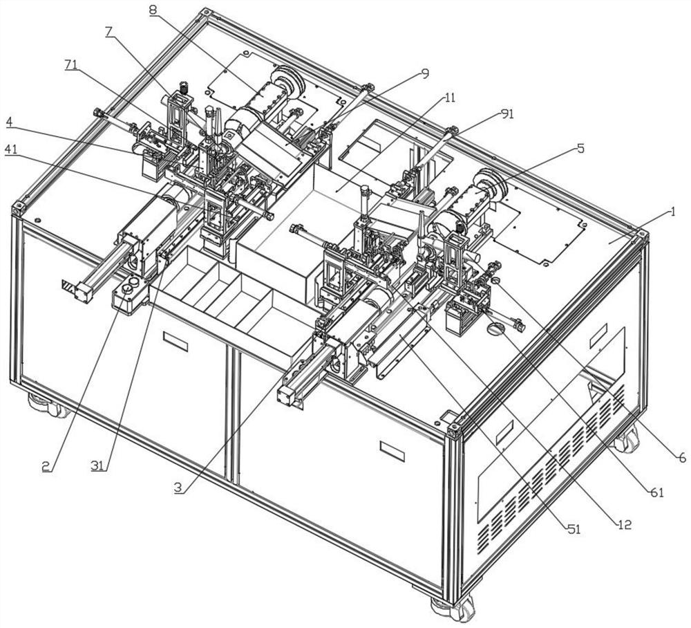
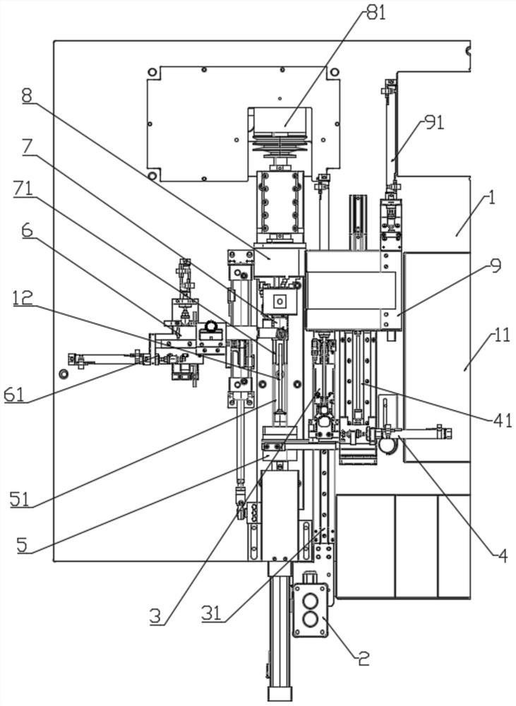
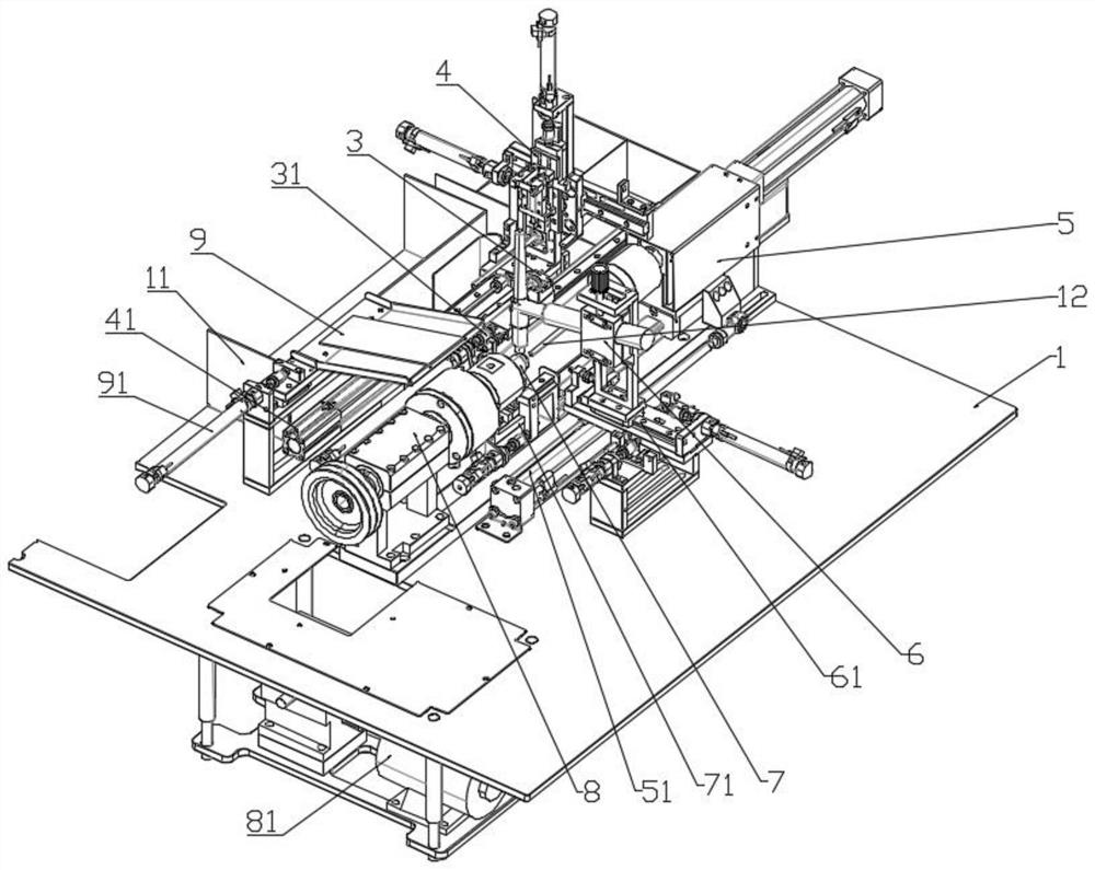
[0023] Device base 1, material receiving frame 11, pre-welding pressure switch 12, coolant 13, device switch 2, feeding mechanism 3, feeding translation mechanism 31, clamping jaw mechanism 4, clamping jaw translation mechanism 41, clamping mechanism 5 , clamping translation mechanism 51, clamping spindle 52, clamping bearing 53, clamping support ring 4, clamping frame oil seal 55, welding mechanism 6, welding translation mechanism 61, fixed locking mechanism 7, fixed locking translation mechanism 71. Rotating mechanism 8, rotating motor 81, rotating cooling casing 82, rotating bearing 83, rotating frame oil seal 84, discharging mechan...


PUM


Abstract

According to the welding device for the pressure switch based on clamping and positioning of the manipulator, two clamping, positioning and welding mechanisms are symmetrically arranged above a device base, and each clamping, positioning and welding mechanism comprises a device switch, a material receiving frame, a feeding mechanism, a clamping jaw mechanism, a clamping mechanism, a welding mechanism, a fixing and locking mechanism, a rotating mechanism and a discharging mechanism; the welding process of the pressure switch is automatically upgraded, the pressure switch is directly manufactured at a time without the steps of manual clamping, welding and discharging, meanwhile, the size of the device is compressed as much as possible, and two sets of automatic production devices can be placed on a base of one device; and meanwhile, a cooling mechanism is further arranged on the clamping device during welding of the pressure switch, welding heat is stably dissipated, and therefore products are prevented from being damaged due to overheating during automatic welding.

Description

technical field [0001] The invention belongs to the technical field of pressure switch positioning welding, and particularly relates to a pressure switch welding device based on manipulator clamping and positioning. Background technique [0002] So far, pressure switches have been widely used as a means of ensuring that various types of machinery can be safely and automatically driven. By presetting a pressure threshold on one side of the pressure switch connected to various devices, excessive fluid pressure generated at the location where the pressure switch is set is detected mechanically and / or electronically, enabling an immediate detection signal to notify various devices. [0003] In order to ensure the constant pressure inside the pressure switch, and the pressure switch needs to be installed in various harsh environments, in this case, it is necessary to further ensure the sealing and stability of its assembly during the assembly of the pressure switch, usually for ...

Claims


Application Information

Patent Timeline
IPC IPC(8): B23K31/02B23K37/00B23K37/04B23K37/047
CPCB23K31/02B23K37/00B23K37/003B23K37/0435B23K37/047Y02P70/50
Inventor 韦小亮何先鹏徐敏
Owner 镇江宏联电工有限公司
Why Eureka
Try Eureka