
Diagnosis system for at least one technical system

a technology of diagnostic system and technical system, applied in the field of diagnostic system, can solve the problems of high cost and the inability to keep experts/expert knowledge in such a center, and achieve the effect of low cost, simple implementation and installation, and low cos

Inactive Publication Date: 2005-06-30
SIEMENS AG
View PDF11 Cites 20 Cited by
  • Summary
  • Abstract
  • Description
  • Claims
  • Application Information

AI Technical Summary

Benefits of technology

[0009] The object of the invention is thus to specify a diagnostics system for at least one technical installation that is simple to implement and install, does not result in high installation costs and is versatile to use.

Problems solved by technology

Thus a short response time to any unacceptable and / or unwanted operating states of the technical installation that arise is essential, because this affects operational reliability and safety in the broadest sense and / or the costs of operating the technical installation.
Nevertheless, at least one suitable expert must be in the remote expert center to produce a diagnosis, because the necessary support tools are only available there.
Keeping experts and / or expert knowledge in such a center inevitably has the disadvantage of high costs however.

Method used


Image

  • Diagnosis system for at least one technical system
  • Diagnosis system for at least one technical system
  • Diagnosis system for at least one technical system

Examples


Embodiment Construction

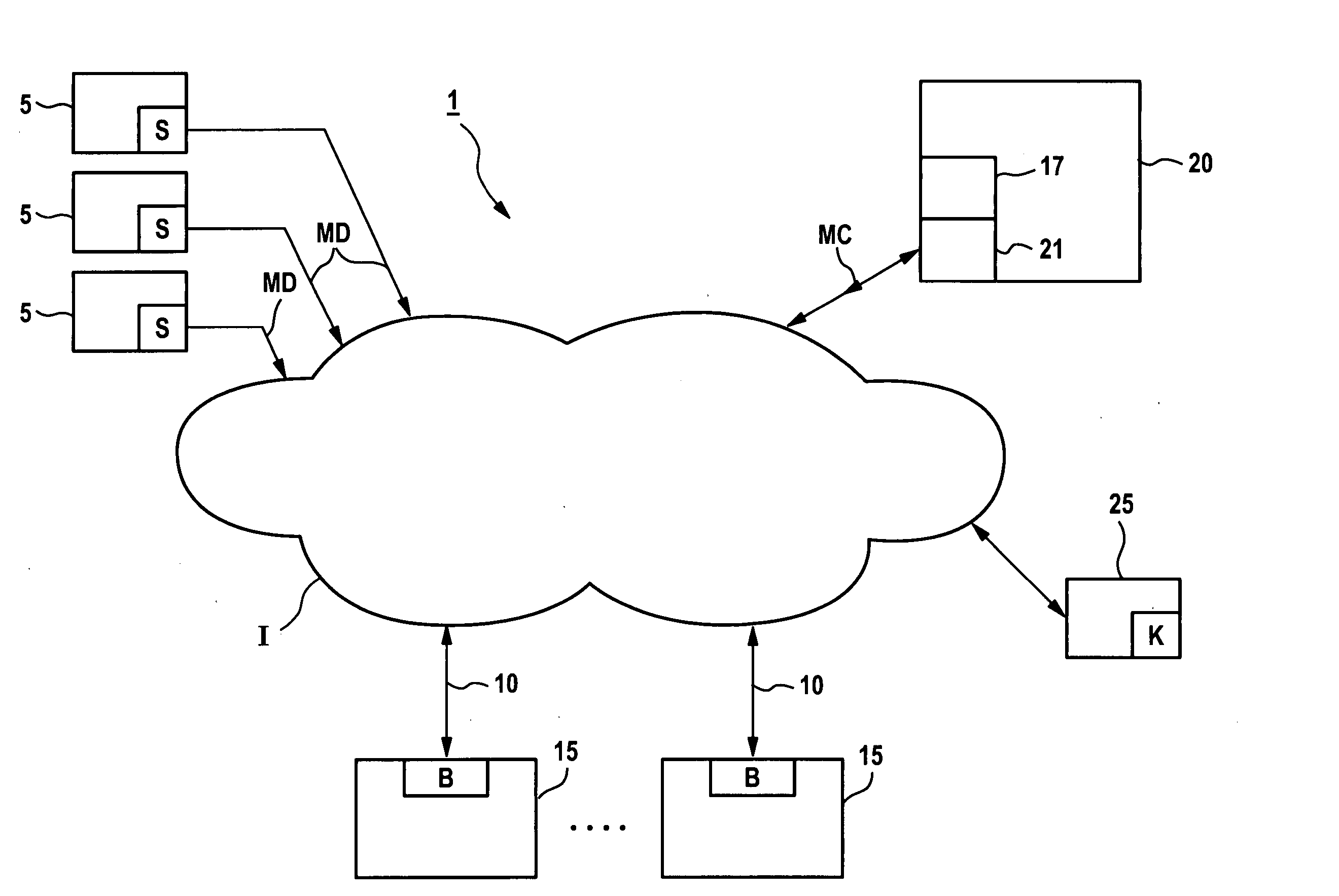
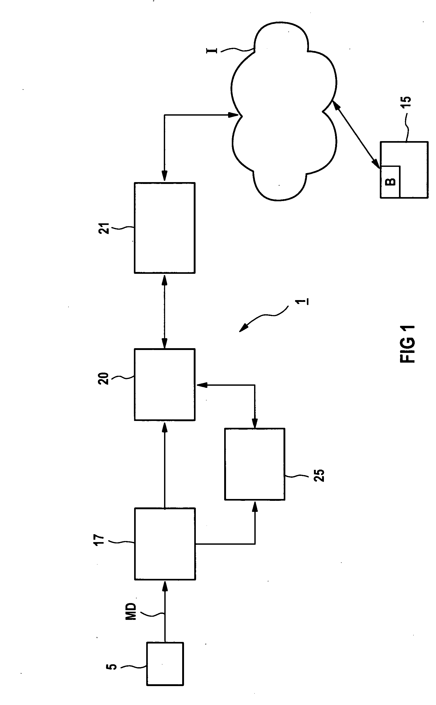
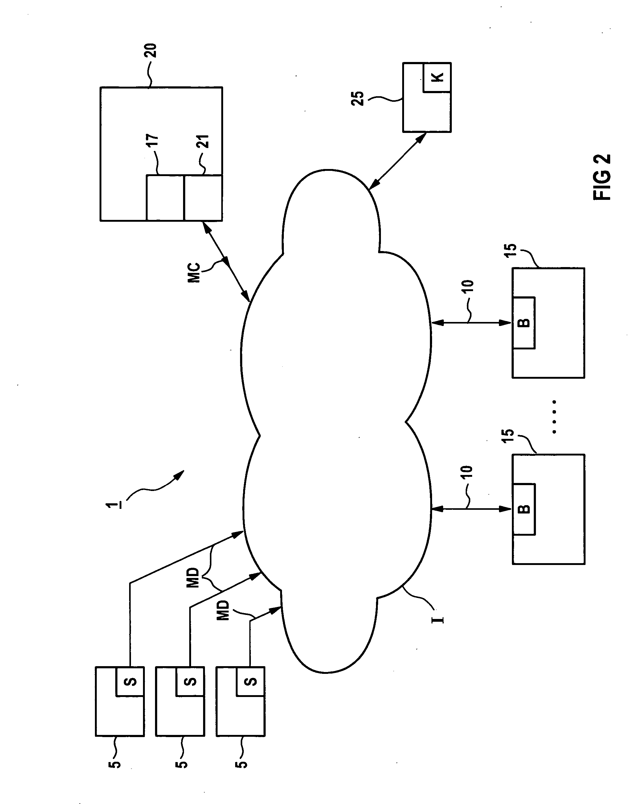
[0047]FIG. 1 shows a diagnostics system 1 according to the invention that contains an acquisition unit 17 for collecting measurement data MD, a memory unit 20, a diagnostics unit 25 and a server unit 21.

[0048] Here the acquisition unit 17 receives the measurement data MD that occurs in the technical installation 5 and is detected there by sensors. The memory unit 20 is connected to the acquisition unit 17 so that the measurement data MD can be stored in the memory unit 20.

[0049] In order to be able to determine current, past and / or expected operating states of the technical installation 5 from the measurement data MD, in the diagnostics system 1 according to the invention shown in FIG. 1, a diagnostics unit 25 is connected to the acquisition unit 17 and the memory unit 20. In this way, both current measurement data MD of the technical installation received by the acquisition unit 17, and historical measurement data from the technical installation 5 from further back in the past th...


PUM


Abstract

The invention relates to a diagnosis system comprising a detection unit for detecting measuring data, a storage unit for storing measuring data, a diagnosis unit for classifying the operational states of the technical system and at least one server unit which is at least connected to the storage unit by means of which machine-readable data based on the HTML-language is produced. Said system enables diagnosis data of a technical system to be transmitted in a simple manner in the form of dynamic HTML pages, especially via the internet and to be evaluated.

Description

CROSS REFERENCE TO RELATED APPLICATIONS [0001] This application is the US National Stage of International Application No. PCT / EP03 / 01864, filed Feb. 24, 2003 and claims the benefit thereof. The International Application claims the benefits of European Patent application No. 02005438.3 EP filed Mar. 8, 2002, both of the applications are incorporated by reference herein in their entirety.FIELD OF THE INVENTION [0002] The invention relates to a diagnostics system for a technical installation, in particular for a power station. BACKGROUND OF THE INVENTION [0003] During operation of a technical installation, as a result of the changing operating conditions over time, a series of operating states arise that must be checked as to whether they are varying within acceptable tolerances and hence are to be classified under normal operation, or whether operating states are occurring, not least occasionally, that put at risk the operation of the installation and / or the operating staff and / or the...

Claims


Application Information

Patent Timeline
IPC IPC(8): G05B23/02
CPCG05B2219/13G05B23/0267G05B2223/06
Inventor GRUHN, MICHAELKUNZE, ULRICHSCHILLER, NORBERT
Owner SIEMENS AG
Learn More