Vehicle wheel balancer system

Active Publication Date: 2005-07-07
HUNTER ENG
View PDF10 Cites 0 Cited by
  • Summary
  • Abstract
  • Description
  • Claims
  • Application Information

AI Technical Summary

Benefits of technology

[0033]FIG. 15 is a representation of a display similar to FIG. 12, indicating that less weight is req

Problems solved by technology

Existing wheel balancer systems suffer from subtle deficiencies in connection with providing compensation for run-out and in tire to rim matching procedures.
Any centering difference with respect to the initial and subsequent mounting of the rim and wheel assembly on the balancer spindle will result in errors in the determination of the rim runout, the assembly force variation, and the tire force variation computations.
This “centering error” can become even more significant with larger wheel assembles, such as those currently entering the market.
Due to variations in wheel design there are usually several adaptors, or combinations of adaptors, that appear to fit the wheel, but actually do not center the wheel adequately on the wheel balancer shaft.
A problem presented by the continued increase in wheel rim and wheel assembly sizes is the effect of a fixed imbalance correction threshold level.
This can result in an operator “chasing” weights on a small or narrow wheel due to the significant effect of the threshold level on imbalances, and a poor balance on larger diameter wheels due to a reduced effectiveness of the threshold level.
This is an advantageous method, but it is not economical for all balancers to have this feature.

Method used


Image

  • Vehicle wheel balancer system
  • Vehicle wheel balancer system
  • Vehicle wheel balancer system

Examples


Embodiment Construction

[0035] The following detailed description illustrates the invention by way of example and not by way of limitation. The description clearly enables one skilled in the art to make and use the invention, describes several embodiments, adaptations, variations, alternatives, and uses of the invention, including what is presently believed to be the best mode of carrying out the invention.

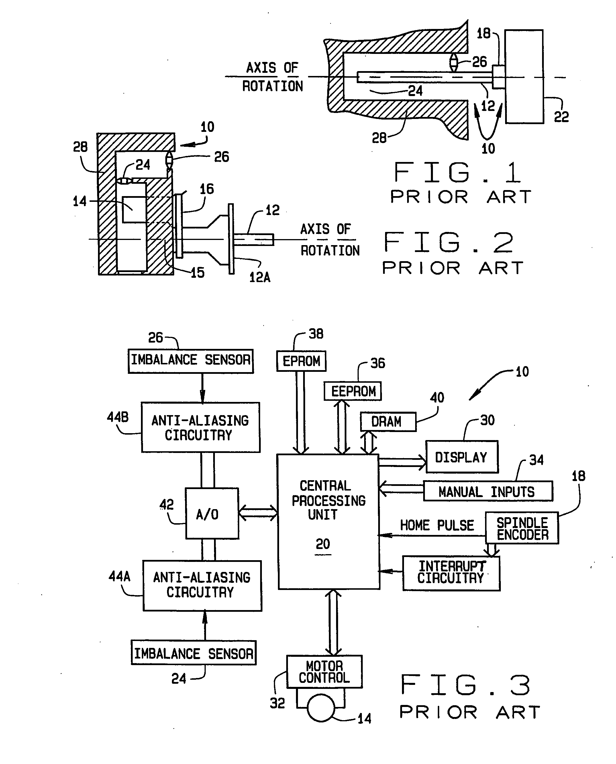
[0036] Turning to the drawings, FIG. 1 illustrates, in simplified form, the mechanical aspects of a wheel balancer 10 suitable for the present invention. The particular balancer shown is illustrative only, since the particular devices and structures used to obtain dimensional and imbalance information related to a rotating body could be readily changed without changing the present invention.

[0037] Balancer 10 includes a rotatable shaft or spindle 12 driven by a suitable drive mechanism such as a motor 14 and drive belt 16. Mounted on spindle 12 is a conventional optical shaft encoder 18 which provides ...


PUM


Abstract

A method for providing a centering check for a rotating body mounted on a wheel balancer based on measuring at least one imbalance parameter. The rotating body is mounted on a spindle of the wheel balancer and an imbalance parameter or runout measurement taken. The mounting of the rotating body on the spindle is then altered, and a second measurement of the imbalance parameter or runout is taken. A processor in the wheel balancer determines if the difference between the first and second measurements exceeds a predetermined threshold value, indicative of off-center mounting of the rotating body one the spindle.

Description

CROSS-REFERENCE TO RELATED APPLICATIONS [0001] The present application is a divisional of, and claims priority to, co-pending U.S. patent application Ser. No. 10 / 648,165 filed on Aug. 26, 2003, which was a continuation-in-part of, and claimed priority from, U.S. patent application Ser. No. 10 / 455,623 filed on Jun. 5, 2003, now abandoned, both of which are hereby incorporated by reference.STATEMENT REGARDING FEDERALLY SPONSORED RESEARCH [0002] Not Applicable. BACKGROUND OF THE INVENTION [0003] The present invention relates generally to automotive service equipment designed to measure imbalance in a vehicle wheel assembly, and in particular, to an improved wheel balancer system configured to adjust an imbalance correction threshold level and to check centering of wheels mounted to the wheel balancer system. [0004] Wheel balancer systems are designed to determine characteristics of a rotating body such as a wheel assembly consisting of a wheel rim and a pneumatic tire, or of a wheel ri...

Claims


Application Information

Patent Timeline
IPC IPC(8): G01M1/02
CPCG01M1/02
Inventor GERDES, MICHAEL D.DOUGLAS, MICHAEL W.SCRIBNER, DAVID M.CLASQUIN, JOELFEERO, WILLIAM B.
Owner HUNTER ENG
Why Eureka
Try Eureka