Method and apparatus of manufacturing stranded bead wire

a technology of bead wire and stranded wire, which is applied in the field of method and an apparatus of manufacturing bead wire, can solve the problems of tensional state, preventing improvement of driving stability, and easy breakdown of steel wire, and achieves smooth continuation

Inactive Publication Date: 2005-07-07
NIWA SYOUKOU CO +1
View PDF10 Cites 26 Cited by
  • Summary
  • Abstract
  • Description
  • Claims
  • Application Information

AI Technical Summary

Benefits of technology

[0036] Using the above constitution, after the magnetic displacement unit advances to the other side, either one of the electromagnets on the magnetic displacement unit and on the magnet support is turned on while the other is turned off. The shift support including the magnet elements is therefore held and transferred alternately between these electromagnets. A transfer of the shift support is completed once per advancing-retracting motion of the magnetic displacement unit. The position of the free rotational reel ...

Problems solved by technology

This causes a problem with easy breakdown of this steel wire 3′.
This causes a difference in tensional states between steel wires, preventing improvement of driving stability.
This arises problems, cau...

Method used


Image

  • Method and apparatus of manufacturing stranded bead wire
  • Method and apparatus of manufacturing stranded bead wire
  • Method and apparatus of manufacturing stranded bead wire

Examples


first embodiment

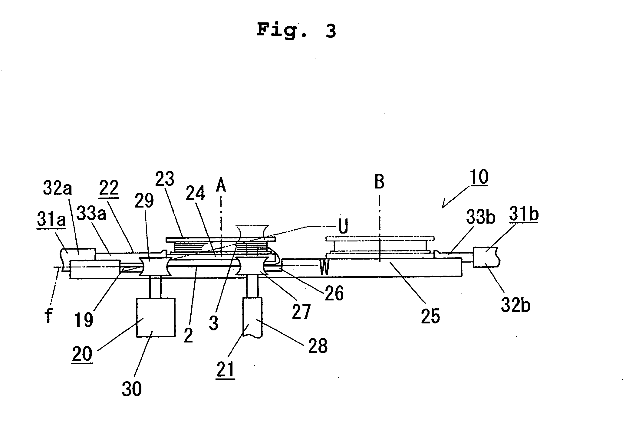
[0059] The stranded bead wire manufacturing apparatus 10 of a first embodiment according to the present invention is described with reference to FIGS. 2 to 4.

[0060] As shown in FIGS. 2 and 3, the stranded bead wire manufacturing apparatus 10 includes: a free rotational reel 23 around which the steel wire 3 to be wound onto the annular core wire 2 is wound to have an outside diameter smaller than that of the annular coil wire 2; a core wire rotating device 20 for supporting the annular core wire 2 and rotating it by rotating rollers 29 which are rotated by drive motors 30; and a core wire up-down device 21 for supporting the annular core wire 2 and displacing the annular core wire 2 up and down by up-down rollers 27 which are actuated upward and downward by up-down cylinders 28. The manufacturing apparatus 10 further includes a reel displacement device 22 having: a movable support 24 for rotatably supporting the free rotational reel 23; guide rails 25 for guiding reciprocation of th...

second embodiment

[0073] A stranded bead wire manufacturing apparatus 11 of a second embodiment according to the present invention is described with reference to FIG. 5.

[0074] The stranded bead wire manufacturing apparatus 11 is adapted to permit a free rotational reel 23 to reciprocate along curved guide rails 34, 34. The guide rails 34, 34 are formed along a circular arc whose center is generally a point where a wound off steel wire 3 around the free rotational reel 23 is tightly wound.

[0075] As is the case with the manufacturing apparatus 10 of the first embodiment, the guide rails 34, 34 have core inserting / removing recesses 26, 26 respectively formed at the points of intersection of the annular core wire 2 and the two guide rails. Ends of the guide rails 34, 34 are assumed inside of the annular core wire 2. A movable support 35 for supporting the free rotational reel 23 for free rotation is also provided, which is movable along the curved guide rails 34, 34.

[0076] Up-down rollers 27, 27, for ...

third embodiment

[0084] A stranded bead wire manufacturing apparatus 12 of a third embodiment according to the present invention is described hereinafter with reference to FIGS. 6 to 9.

[0085] As shown in FIGS. 6 and 7, as is the case with the manufacturing apparatus 10 of the first embodiment, the stranded bead wire manufacturing apparatus 12 includes a core wire rotating device 20 for rotating the annular core wire 2, and a free rotational reel 23 around which the steel wire 3 to be wound onto the annular core wire 2 is wound to have an outside diameter smaller than that of the annular coil wire 2. Further, the manufacturing apparatus 12 includes a reel displacement device 42 having: a core wire up-down device 21 for displacing the annular core wire 2 up and down; and linear guide rails 25, 25 for guiding reciprocation of the free rotational reel 23. The guide rails 25, 25 are provided with core inserting / removing recesses 26, 26, respectively. As is the case with the first embodiment, around the ...


PUM

PropertyMeasurementUnit
Forceaaaaaaaaaa
Diameteraaaaaaaaaa

Abstract

A method for manufacturing a stranded bead wire includes rotating an annular core wire in the circumferential direction thereof, while repeating a pseudo linear reciprocating motion of a reel around which a steel wire is wound to have an outside diameter smaller than that of the annular core wire, in which motion the reel is displaced approximately in a radial direction of the annular core wire in a way that it is relatively displaced in an approach direction on one side of a plane crossing the annular core wire, then passed through inside thereof, and displaced in a direction of distance increase on the other side of the plane, whereby the steel wire is tightly wound onto the annular core wire in a spiral pattern. A stranded bead wire manufacturing apparatus includes a core wire rotating means for rotating an annular core wire; a free rotational reel around which a steel wire is wound to have an outside diameter smaller than that of the annular core wire; and a reciprocable displacement means for repeating the pseudo linear reciprocating motion of the free rotational reel relative to the annular core wire, wherein, while the annular core wire is rotated, the free rotational reel repeats the pseudo linear reciprocating motion, whereby the steel wire is tightly wound onto the annular core wire in a spiral pattern.

Description

CROSS-REFERENCE TO RELATED APPLICATION [0001] This application is a Continuation of International Application Serial No. PCT / JP2003 / 010241 filed Aug. 12, 2003 and claims the benefit of Japanese Patent Application Nos. 2002-280054 filed Aug. 20, 2002; 2002-280055 filed Aug. 20, 2002 and 2002-382651 filed Nov. 25, 2002 both of which are incorporated by reference herein in their entireties. The International Application was published in Japanese on Mar. 4, 2004 as WO 2004 / 018187 A1.FIELD OF THE INVENTION [0002] This invention relates to a method and an apparatus of manufacturing a bead wire which is embedded into a bead portion of a tire used for cars, motorcycles, aircrafts or the like to improve a force for the tire to tightly joint a wheel. BACKGROUND OF THE INVENTION [0003] A bead wire is disposed in a bead portion of a tire fitted to a certain bead seat portion of a wheel, which is designed to tight-fit the wheel in the circumferential direction to improve the force for the tire t...

Claims


Application Information

Patent Timeline
IPC IPC(8): B21F7/00B29D30/48B60C15/04
CPCB29D30/48B21F7/00
Inventor NIWA, TOMOMICHI
Owner NIWA SYOUKOU CO
Why Eureka
Try Eureka