
Radiographic imaging apparatus and method, and console device

a radiographic imaging and console technology, applied in the field of radiographic imaging apparatus and method, can solve the problems of affecting the smooth handling of the electronic cassette, affecting the operation of the console device, so as to achieve the effect of continuing radiographic imaging smoothly

Active Publication Date: 2018-11-08
FUJIFILM CORP
View PDF0 Cites 0 Cited by
  • Summary
  • Abstract
  • Description
  • Claims
  • Application Information

AI Technical Summary

Benefits of technology

This solution effectively reduces false communication failure alerts during radiographic imaging, maintaining workflow efficiency by distinguishing between actual failures and operational states, thus minimizing disruptions and image degradation.

Problems solved by technology

Assuming that a cable is physically connected to the electronic cassette for communication with the console device, the cable is likely to obstruct smooth handling of the electronic cassette.
Assuming that noise of radio waves occurs in image readout to converting charge of pixels into an image signal in the sensor panel, the noise is superimposed with a radiation image to create degradation in its image quality.
The wireless access point always generates the beacon in the structure incorporated in the electronic cassette, so that the beacon may cause the degradation.
However, a problem arises with the regulation of the beacon.
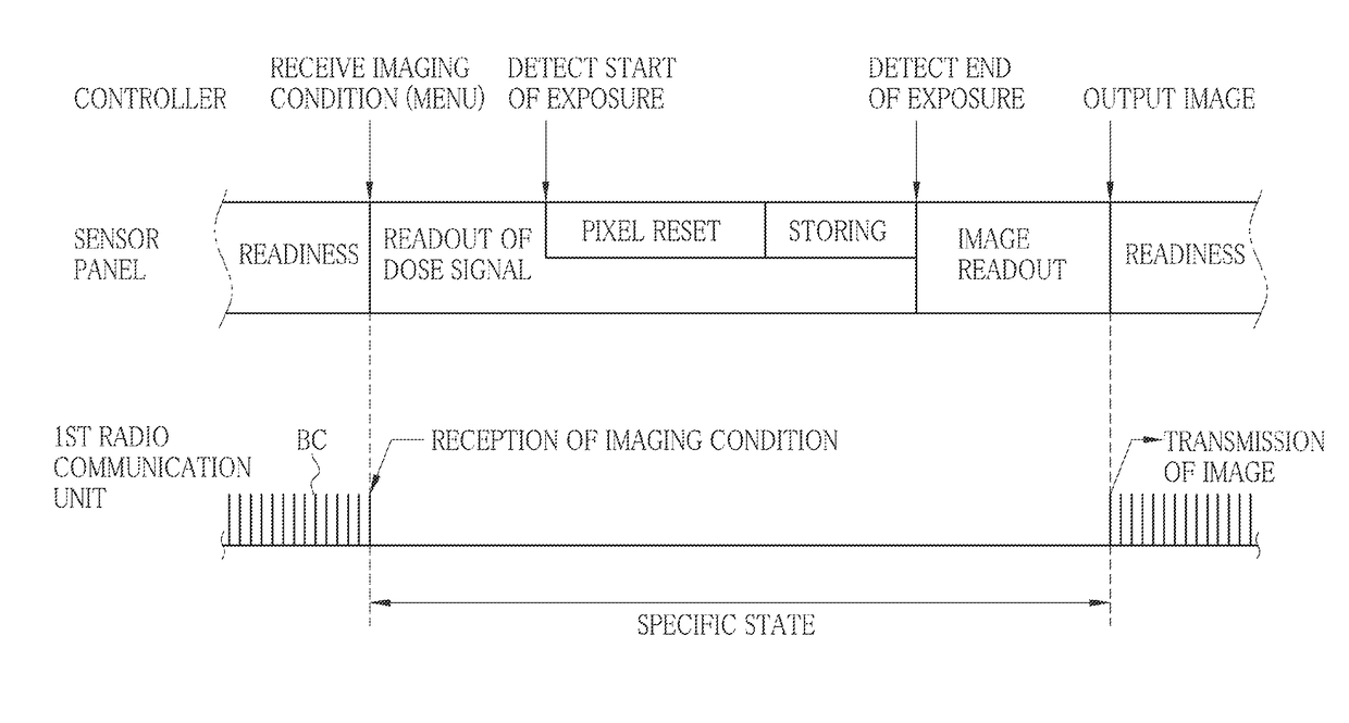
A difficulty occurs in reception of the beacon at a console device while the electronic cassette regulates the beaconing in the specific state.
Even though no communication failure has occurred in the reception of the beacon during the regulation, false alert may be generated because of improper judgment of disconnection with the electronic cassette on the basis of a false communication failure.
It is likely to take waiting time to patients with objects to be imaged, to lower efficiency in the imaging remarkably specially during the operator's tasks for recovery after the alert.

Method used


Image

  • Radiographic imaging apparatus and method, and console device
  • Radiographic imaging apparatus and method, and console device
  • Radiographic imaging apparatus and method, and console device

Examples


first embodiment

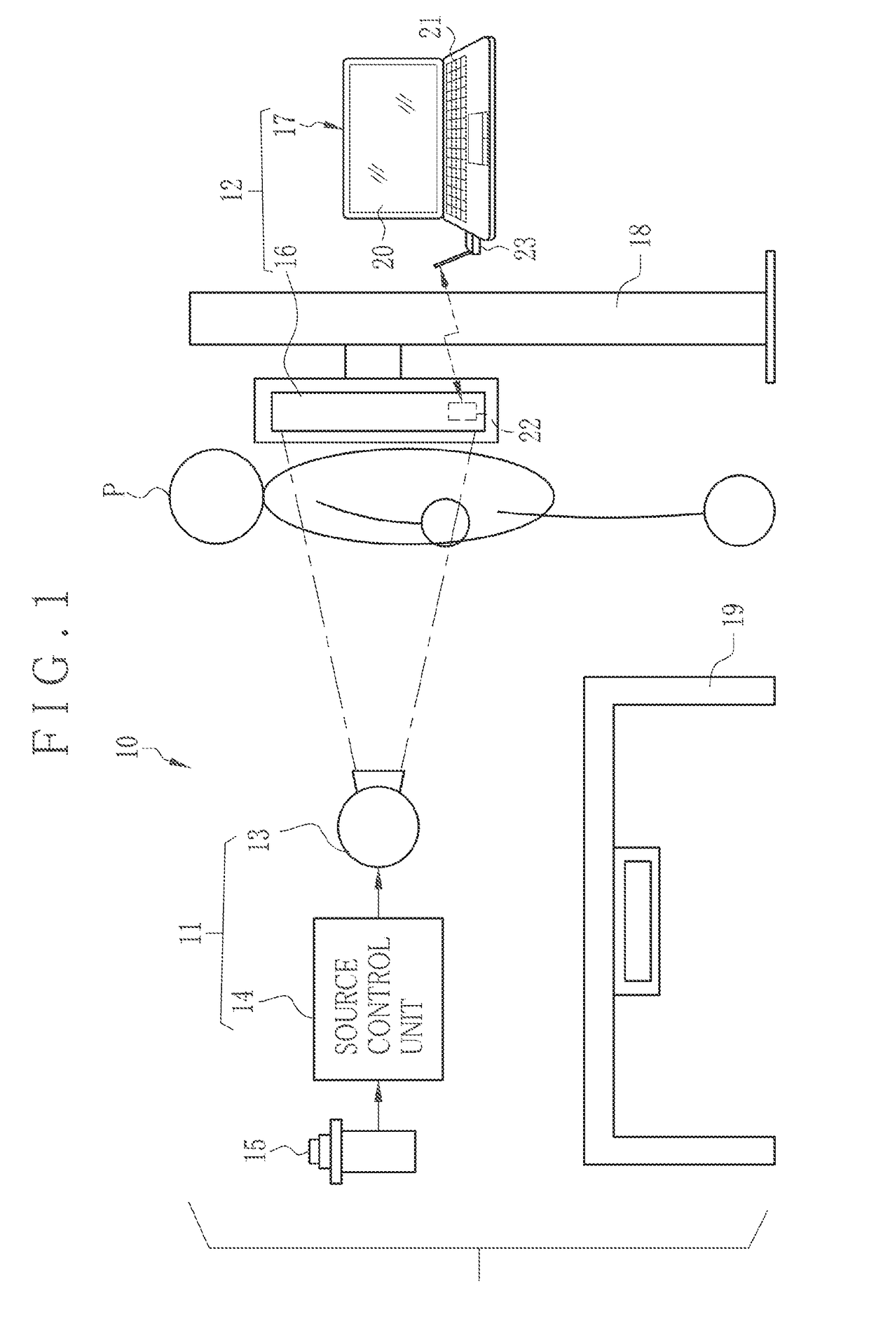
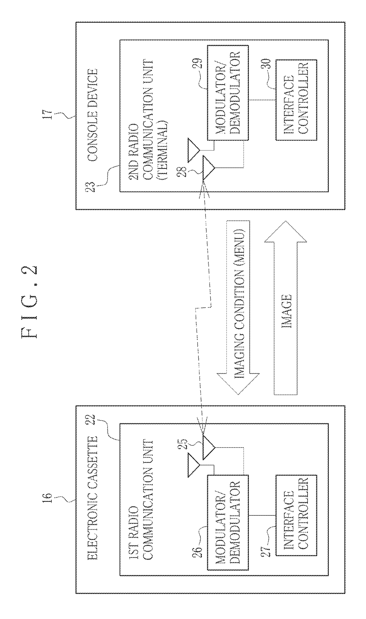
[0060]In FIG. 1, a radiographic imaging system 10 or X-ray imaging system includes a radiation generator 11, and a radiographic imaging apparatus 12 or X-ray imaging apparatus, and is installed in a storage room of a radiology department in a hospital facility. The radiation generator 11 includes a radiation source 13 or X-ray source and a source control unit 14. A radiation switch 15 is connected to the source control unit 14. The radiographic imaging apparatus 12 includes an electronic cassette 16 for radiographic imaging, and a console device 17 or system terminal device.

[0061]The examination room contains the radiographic imaging system 10, a floor stand 18 for radiographic imaging, and a patient table 19 for radiographic imaging. The floor stand 18 is used for imaging a patient body P in a standing posture (upright posture). The patient table 19 is used for imaging the patient body P in a lying posture. The radiation source 13 is used commonly in combination with the floor stan...

second embodiment

[0142]In the first embodiment, the display panel 20 and the speaker 78 are disabled by a state without a command signal from the alert manager 89 for the purpose of avoiding the alert notification in the specific state. However, the communication failure detector 87 can be disabled for the purpose of avoiding the alert notification in the specific state instead of controlling the display panel 20 and the speaker 78.

[0143]In FIG. 17, the communication failure detector 87 does not output information of occurrence of a communication failure even in case a state without receiving the beacon BC in the second radio communication unit 23 is continued in the timeout period TO in the specific state. The alert manager 89 does not output a command signal for alert notification either, because no information of occurrence of a communication failure is output. Thus, it is possible to avoid generation of alert notification in the specific state by disabling the communication failure detector 87.

third embodiment

[0144]A method for avoiding generation of alert notification in the specific state can be a method of elongating the timeout period TO in addition to the first embodiment of the method of turning off the display panel 20 and the speaker 78 and the second embodiment of the method of disabling the communication failure detector 87.

[0145]The alert manager 89 in the specific state determines a timeout period TOL of FIG. 18 in the communication failure detector 87, as a longer value than the timeout period TO of the first embodiment (timeout period TO in the non-specific state).

[0146]The timeout period TOL is a sum of expected time and very short time for safety, the expected time being an empirically obtained period where the operational state of the electronic cassette 16 is the specific state of the first embodiment, namely, from reception of the various data in the first radio communication unit 22 inclusive of the imaging condition (transmission of the data from the second radio com...


PUM


Abstract

A radiographic imaging apparatus includes an electronic cassette and a console device for radio communication with the electronic cassette. The electronic cassette includes a transmitter for transmitting a beacon for the radio communication. A regulation unit regulates beaconing of the beacon in a predetermined specific state among plural operational states. The console device includes a receiver for receiving the beacon. A communication failure detector checks whether a communication failure has occurred in the radio communication according to a receiving state of the beacon in the receiver. A display panel or speaker generates alert notification to notify the communication failure assuming that the communication failure detector judges that the communication failure has occurred. An operational state detector checks whether the electronic cassette is in the specific state. An alert manager avoids generation of the alert notification while the operational state detector judges that the electronic cassette is in the specific state.

Description

CROSS-REFERENCE TO RELATED APPLICATION[0001]This application is a Divisional Application of U.S. application Ser. No. 15 / 164,026, filed May 25, 2016, which claims priority under 35 USC 119 from Japanese Patent Application No. 2015-114764, filed 5 Jun. 2015, the disclosures of each of which are incorporated by reference herein.BACKGROUND OF THE INVENTION1. Field of the Invention[0002]The present invention relates to a radiographic imaging apparatus and method and a console device. More particularly, the present invention relates to a radiographic imaging apparatus and method and a console device in which a problem of occurrence of a communication failure can be coped with suitably to continue radiographic imaging smoothly in a workflow.2. Description Related to the Prior Art[0003]A radiographic imaging apparatus or system, or X-ray imaging apparatus or system is known in the field of the medical diagnosis for imaging of a patient body by use of radiation or X-rays. The radiographic i...

Claims


Application Information

Patent Timeline
Patent Type & Authority Applications(United States)
IPC IPC(8): A61B6/00G08B21/18G08B5/36H04W24/04G08B29/18
CPCG08B21/185A61B6/586G08B5/36H04W24/04A61B6/4283G08B29/185A61B6/563
Inventor KUDOU, YOSHIMITSU
Owner FUJIFILM CORP
Learn More