Masking tape applicator

a tape applicator and tape technology, applied in the field of masking tape applicators, can solve the problems of not applying the tape at the exact location or accuracy, all known prior art devices are too expensive for most homeowners to use, and achieve the effect of great accuracy and better accommodating the wide variance in widths

Active Publication Date: 2005-07-07
3M INNOVATIVE PROPERTIES CO
View PDF9 Cites 15 Cited by
  • Summary
  • Abstract
  • Description
  • Claims
  • Application Information

AI Technical Summary

Benefits of technology

[0005] The present invention provides a device for applying tape from a roll of tape (e.g., masking tape) along a surface to be protected with an edge of the tape extending along a juncture between the surface to be protected and a surface to be treated that is disposed at about a right angle with respect to the surface to be protected, which device has some structure that is similar to the structure of the device described in U.S. patent application Ser. No. 10 / 179,602, but includes a novel pressure application structure that can apply the tape at exact desired locations with great accuracy, and can apply the tape while moving the device in either of two directions along the surface to be protected, but does not require providing as close a tolerance between tape contact parts of inner surfaces for housing side portions and a roll of tape to be applied by the device, thereby better accommodating the wide variance in widths of different production rolls of tape of the same nominal width.
[0009] This structure has been found to apply the tape at exact desired locations with great accuracy, and can apply the tape while moving the device in either of two directions along the surface to be protected, while only requiring a tolerance of about 0.06 inch or 0.15 cm between the inner surfaces of the housing portions and a roll of tape to be applied by the device. This tolerance can be allowed because pressure applied to the tape being dispensed by the end portions of the pressure application structure in the device will cause the side surface of the roll of tape to move toward or into contact with the tape contact part of the inner surface of the housing portion being slid along the surface to be treated.
[0010] A modified version of the above described device can also be made in which the means for journaling the roll of tape still affords free rotation of the roll of tape, but does not allow free axial movement of the roll of tape between the portions of the housing. In this modified version a user of the device must manually move the roll of tape into contact with the tape contact part of the inner surface for the housing portion that is being moved along a surface to apply the tape, however, this modified device provides the advantage that it can be used to apply rolls of tape that have an axial width dimension that is significantly less than the dimension between the tape contact parts of the inner surfaces for the housing portions. Thus, the same dispenser can be used to accurately apply tapes of different widths.

Problems solved by technology

While such prior art devices can be useful for this purpose, all such known prior art devices either are too expensive for use by most homeowners or the like, do not apply the tape at the exact location or with the accuracy that is desired, and / or lack versatility in that the tape can not be applied while moving the device in either of two directions along the surface to be protected without repositioning the roll of tape in the device.

Method used


Image

  • Masking tape applicator
  • Masking tape applicator
  • Masking tape applicator

Examples


first embodiment

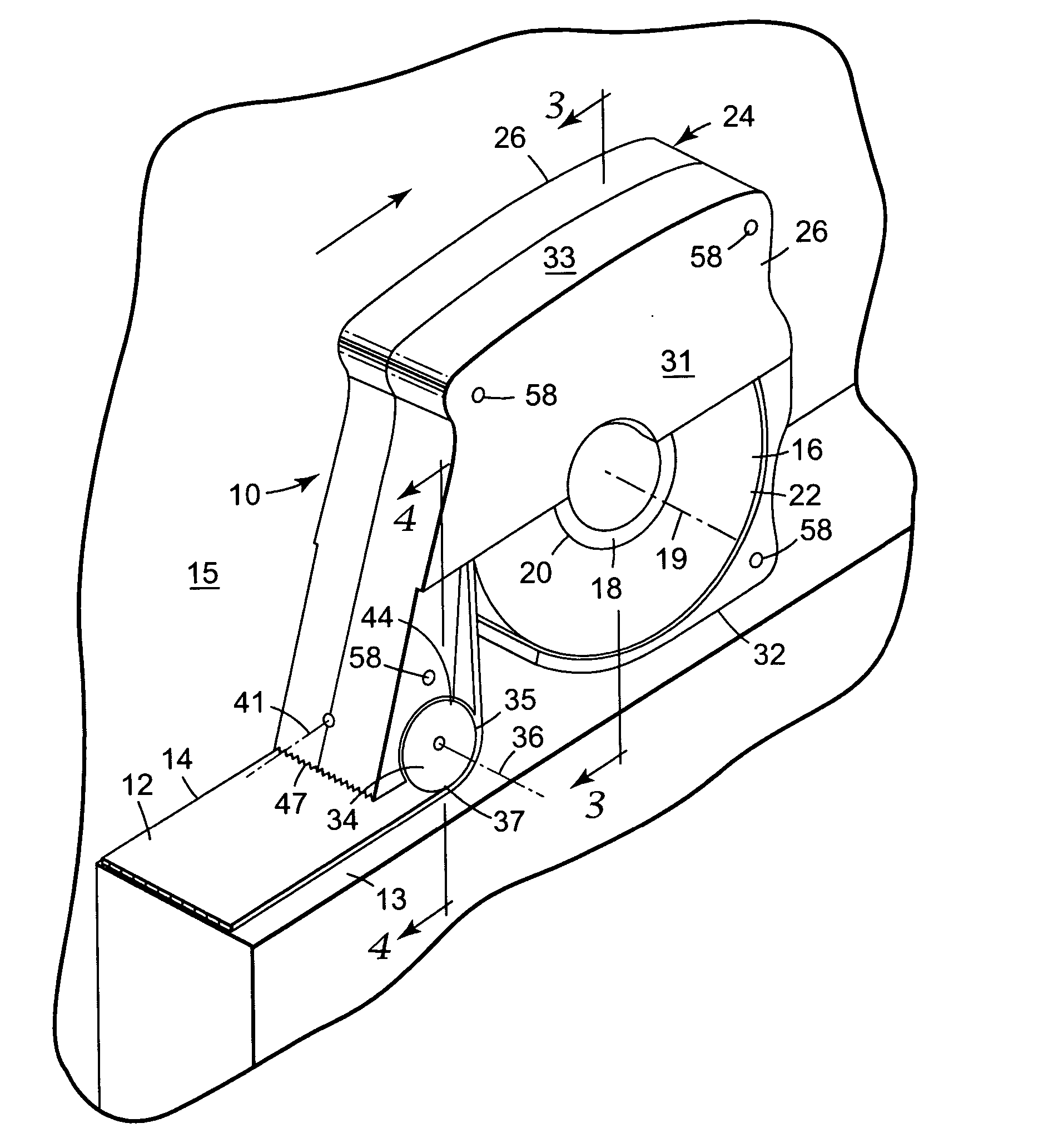
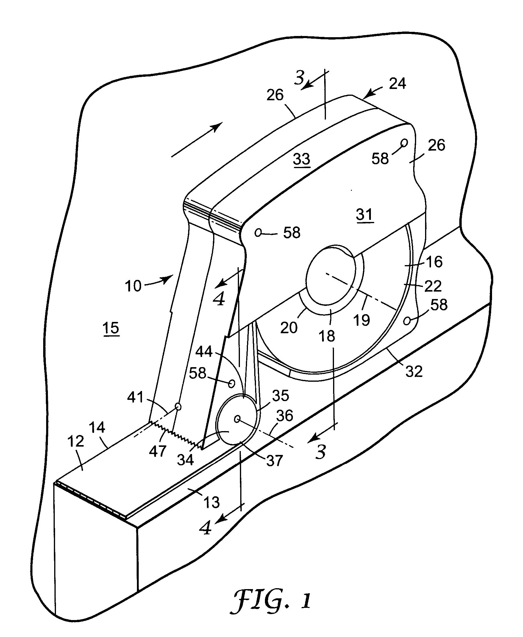
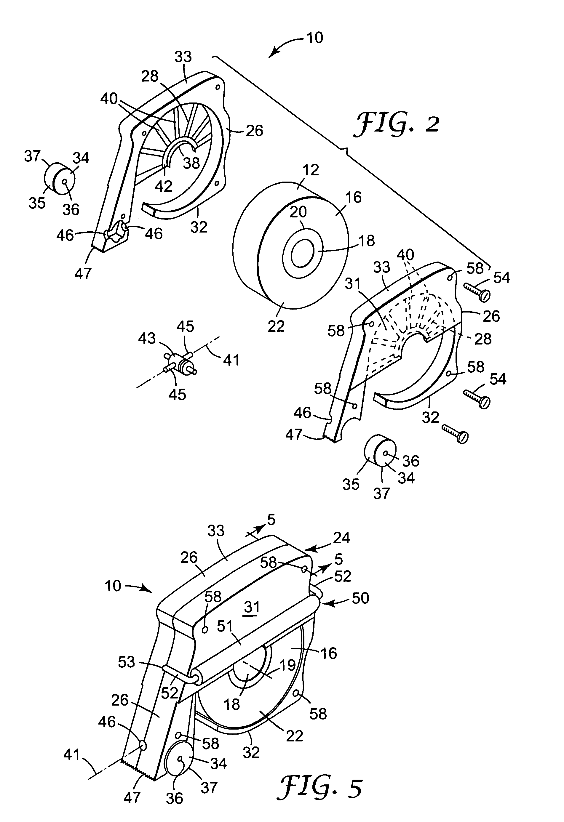
[0021] Referring now to FIGS. 1 through 4 of the drawing there is illustrated a device 10 according to the present invention that can be manually used to apply a length of tape 12 along a surface 13 to be protected (e.g., the side surface 13 of a window or door molding) with an edge 14 of the tape 12 extending along a juncture between the surface 13 to be protected and a surface 15 to be treated (e.g., a wall 15 to be painted) disposed at about a right angle with respect to the surface 13 to be protected.

[0022] The device 10 includes or is adapted to receive a roll 16 of tape (e.g., masking tape of the type commercially available from 3M Company, St. Paul, Minn., that may nominally be {fraction (1 / 2, 3 / 4)}, 1, or 2 inches or 1.3, 1.9, 2.5, or 5 centimeters wide) including a core 18 having an axis 19, a cylindrical periphery 20 around the axis 19, and including a length of the tape 12 (e.g., masking tape) that comprises a backing having opposite major surfaces extending between oppos...

second embodiment

[0036]FIGS. 6, 7, and 8 illustrate a second embodiment for a device 60 according to the present invention that includes an alternative structure for mounting two pressure rollers 61 on a housing 24′ for rotation about a common axis 62 and for pivotal movement about a pivot axis 64, which alternate structure could be substituted for the structure for mounting he pressure rollers 34 on the housing 24 for rotation about their common axis 36 and for limited pivotal movement about the pivot axis 41 described above. Except for that alternate structure described below, the device 60 and a roll of tape 16a in the device 60 have essentially the same structures as the device 10 and the roll of tape 16 described above and have applied to them the same reference numerals to which has been added the suffix “a”. In the alternative structure illustrated in FIGS. 6, 7, and 8, the rollers 61 are integrally fixed on the opposite end portions of an axle 66 that extends between the rollers 61. The axle...

third embodiment

[0037]FIG. 9 illustrates a device 80 according to the present invention that includes an alternative means for journaling the roll of tape 16b which, like the means for journaling the rolls of tape 16 and 16a in the devices 10 and 60, affords free rotation of the roll of tape 16b, but unlike those means, does not allow free axial movement of the roll of tape 16b between the portions 26b of the housing 24b. Except for that alternate structure described below, the device 80 and a roll of tape 16b in the device 80 could have essentially the same structures as either the device 10 and the roll of tape 16 or the device 60 and the roll of tape 16a described above and have applied to them the same reference numerals to which has been added the suffix “b”. In the device 80, the means for journaling the roll of tape 16b comprises a cylindrical roller 82 having an axis 84, and coaxial trunnions 86 projecting from its opposite ends mounted for rotation in the housing portions 26b. The roller 8...


PUM

PropertyMeasurementUnit
angleaaaaaaaaaa
angleaaaaaaaaaa
angleaaaaaaaaaa

Abstract

A device for applying tape from a roll of tape (e.g., masking tape) along a surface to be protected with an edge of the tape extending along a juncture between the surface to be protected and a surface to be treated disposed at about a right angle with respect to the surface to be protected. The device includes a two portion housing around and journaling the tape roll, each portion having a tape contacting part of its inner surface in a first plane, and having in a second plane a guide part of its outer surface adapted to be slid along the surface to be treated. The first and second planes on each of the housing portions can be parallel or at a small angle with respect to each other so that they intersect along an application side of the housing. A pressure application structure is mounted on the housing with an outer edge each end of the pressure application structure at the intersection (if they intersect) of the first and second planes for a different adjacent one of the housing portions. The pressure application structure is mounted on the housing for limited pivotal movement in a plane at about a right angle with respect to a plane along the guide surface. The roll of tape can be mounted in the housing for free rotation and axial movement. Tape from the roll extends around the periphery of the pressure application structure so that the dispenser can be manually positioned with either housing portion against the surface to be treated and moved to apply the tape, whereupon pressures applied to the tape being dispensed by the pressure application structure in the device will cause the side surface of the roll of tape to move toward or into contact with the tape contact part of the inner surface of the housing portion being slid along the surface to be treated so that the tape is accurately applied.

Description

FIELD OF THE INVENTION [0001] The present invention relates to devices for applying tape from a roll of tape (e.g., masking tape) along a surface to be protected with an edge of the tape extending along a juncture between the surface to be protected and a surface to be treated (e.g., painted) that is disposed at about a right angle with respect to the surface to be protected. BACKGROUND OF THE INVENTION [0002] Many devices have been designed for use to apply tape from a roll of tape (e.g., masking tape) along a surface to be protected with an edge of the tape extending along a juncture between the surface to be protected (e.g., a door or window molding) and a surface to be treated (e.g., a wall to be painted) that is disposed at about a right angle with respect to the surface to be protected. U.S. Pat. No. 5,269,871 (Longworth et al.) and U.S. Pat. No. 6,302,177 (Gruber) provide illustrative examples. While such prior art devices can be useful for this purpose, all such known prior ...

Claims


Application Information

Patent Timeline
Patent Type & Authority Applications(United States)
IPC IPC(8): B05B15/04B65H35/00
CPCB05B15/0456B65H35/0033Y10T156/18Y10T156/1795Y10T156/1788B65H35/0073B05B12/24
Inventor SOMERS, MICAH T.HALLEE, NATHANIEL R.PITZEN, JAMES F.
Owner 3M INNOVATIVE PROPERTIES CO
Why Eureka
Try Eureka