Metal porous body manufacturing method

a metal body and manufacturing method technology, applied in the field of metal porous body manufacturing, can solve the problems of significant formation of coarse pores, reduced cooling rate in the inner part of metal bodies, and difficult to form uniform pores

Inactive Publication Date: 2005-07-07
NAKAJIMA HIDEO
View PDF3 Cites 21 Cited by
  • Summary
  • Abstract
  • Description
  • Claims
  • Application Information

AI Technical Summary

Benefits of technology

[0007] The inventors have conducted intensive research to achieve the above objectives. The inventors found that the following outstanding effectiveness is achieved by a specific process using a floating zone melting method which comprises the steps of partially melting the starting metal material while moving the material; dissolving various types of gases into the molten metal; and solidifying the molten metal. That is, according to the process, the amount of a gas which dissolves into a molten metal can be controlled by suitably determining the kind of gas to be used, the combination of gases, gas pressure, etc. and further pore shape, pore size, porosity, etc. can be arbitrarily controlled by selecting the moving rate of a starting metal material, the cooling method, etc. Moreover, the inventors found that the process can produce a porous body with micro pores elongated in one direction even when using a long or large-sized starting metal material of low thermal conductivity. The present invention has been completed based on these novel findings.

Problems solved by technology

However, when these processes are applied to the cases where commonly-used materials for practical use such as steels, stainless steels, etc. are used, cooling rates decrease in the inner part of metal body due to the low thermal conductivity thereof, which results in a significant formation of coarse pores, and thus it is difficult to form uniform pores.
Such a porous body with uneven pore sizes is disadvantageous in that high strengths cannot be ensured because greater stresses are exerted around larger pores when a load is applied.
Moreover, such a porous body cannot be used as a filter which needs uniformity of pore diameter.

Method used


Image

  • Metal porous body manufacturing method
  • Metal porous body manufacturing method
  • Metal porous body manufacturing method

Examples


example 1

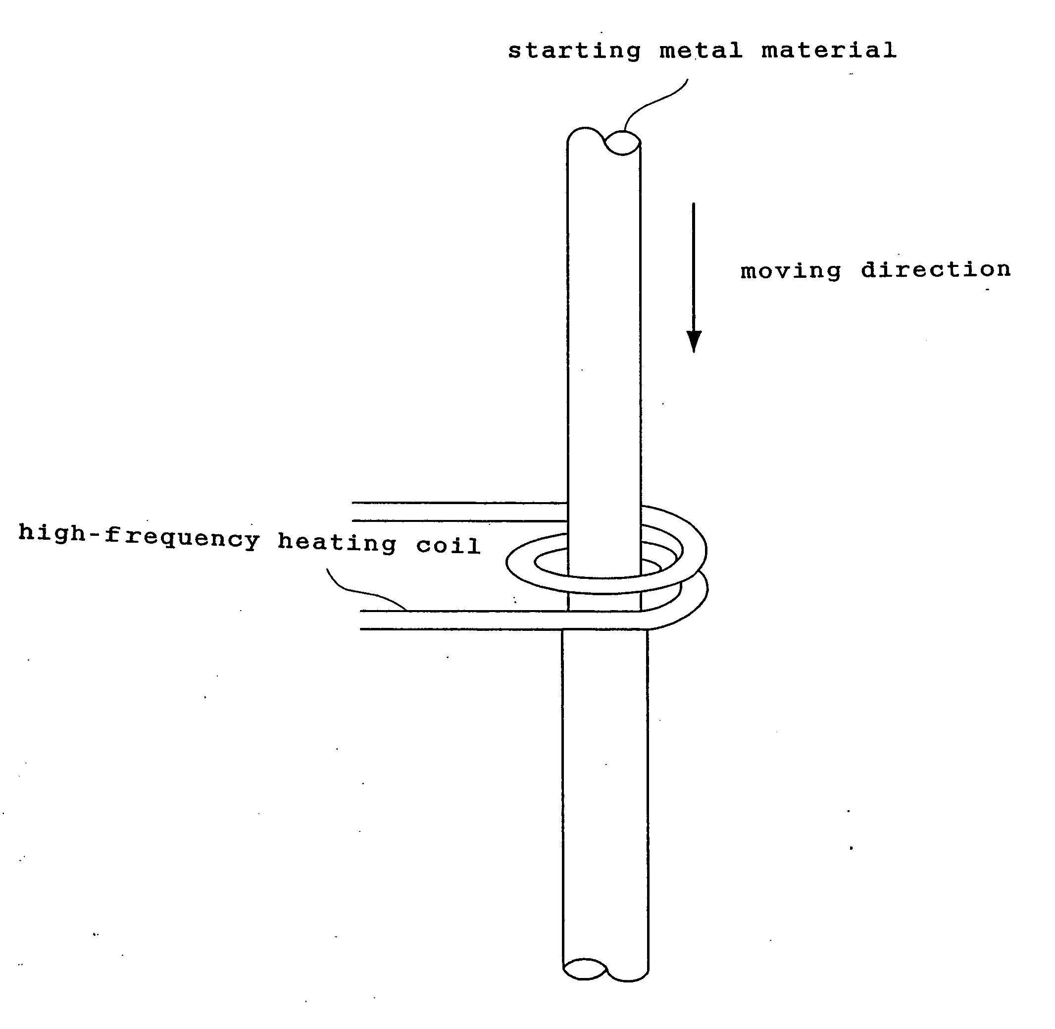
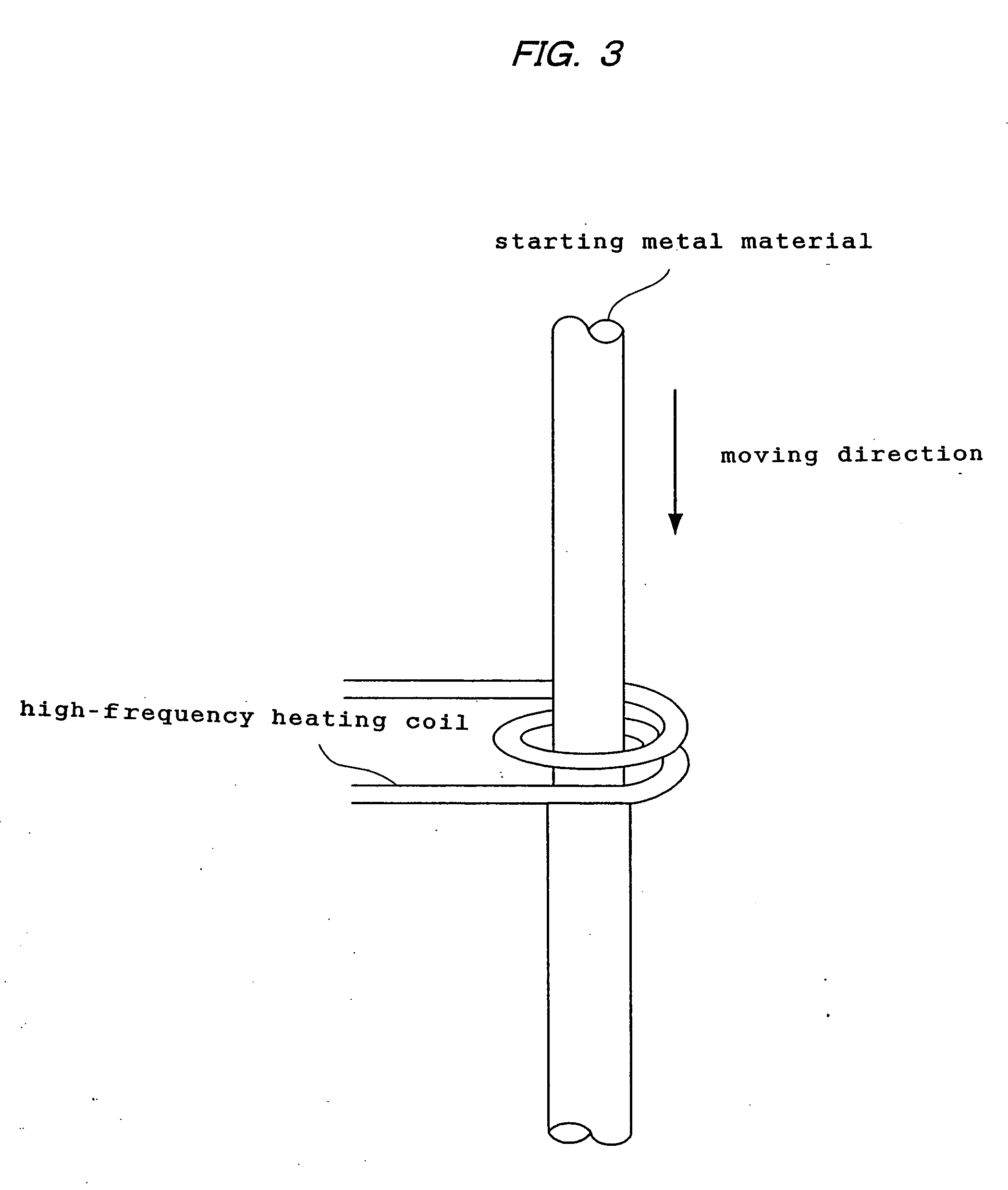
[0086] Various types of porous metal bodies varying in porosity were produced using iron of 99.99% purity as a starting metal material and employing the apparatus shown in FIG. 8. As the starting metal material, a cylindrical material 10 mm in diameter and 1,000 mm long was used.

[0087] Nitrogen or hydrogen was supplied into the apparatus as the dissolving gas, and argon was further supplied so as to control the porosity, where necessary.

[0088] The moving rate of the starting metal material was set at 160 μm / second. A high-frequency heating coil was used as the heating means, and the temperature of the melting portion was maintained at 1,555° C.

[0089]FIG. 9 is a graph showing the relationship between the porosity and the tensile yield stress of the porous metal material obtained. FIG. 10 is a graph showing the relationship between the porosity and the tensile strength. The graph in FIG. 9 shows measurement results on tensile yield stresses in a direction parallel to a growth direc...


PUM

PropertyMeasurementUnit
pressureaaaaaaaaaa
pressureaaaaaaaaaa
melting pointaaaaaaaaaa

Abstract

The present invention provides a process for producing a porous metal body, the process comprising: melting part of a starting metal material in succession while moving the material by a floating zone melting method under a gas atmosphere to dissolve a gas into a resultant molten metal; and solidifying the molten metal zone in succession by cooling. According to the process of the present invention, even when the starting metal material is of low thermal conductivity, a porous metal body with uniform and micro pores grown only in the longitudinal direction is produced.

Description

TECHNICAL FIELD [0001] The present invention relates to a process for the production of a porous metal body. BACKGROUND OF THE INVENTION [0002] In recent years, porous material bodies such as porous metals have been intensively studied, and are in progress in the development toward practical use as filters, hydrostatic bearings, medical instruments, sporting goods and the like. [0003] U.S. Pat. No. 5,181,549, for example, describes a process for the production of a porous body such as a porous metal. More specifically, the production process comprises dissolving hydrogen or a hydrogen-containing gas under pressure into a molten metal material, and then cooling the molten metal to solidify the same under the controlled temperature and pressure conditions. [0004] Japanese Unexamined Patent Publication No. 10-88254 discloses a process for producing a porous metal which comprises the steps of melting a metal under a pressurized gas atmosphere and solidifying the molten metal, the metal ...

Claims


Application Information

Patent Timeline
Patent Type & Authority Applications(United States)
IPC IPC(8): B22D11/00B22D25/00B22D25/02
CPCB22D25/005B22F2998/00C22C2001/086C22C1/08C22C1/086B22D25/02B22D11/00
Inventor NAKAJIMA, HIDEO
Owner NAKAJIMA HIDEO
Why Eureka
Try Eureka