Floating zone melting apparatus

a melting apparatus and floating zone technology, applied in the direction of zone melting liquid, single crystal growth, chemistry apparatus and processes, etc., can solve the problems of difficult to grow a single crystal with a diameter larger, difficult to uniformly dissolve and deposition, and inconvenient dissolution and deposition, etc., to achieve the effect of reducing the load of infrared ray irradiation

Inactive Publication Date: 2010-12-09
CRYSTAL SYST
View PDF8 Cites 14 Cited by
  • Summary
  • Abstract
  • Description
  • Claims
  • Application Information

AI Technical Summary

Benefits of technology

[0069]In accordance with the present invention, a plurality of infrared ray irradiation means are disposed at two stages in such a manner that a sample is irradiated with infrared ray from two directions of an upper direction and a lower direction, and an irradiation angle and an irradiation amount of infrared rays of the infrared ray irradiation means are controlled corresponding to an actual melting property while independently controlling the infrared ray irradiation means disposed at two stages. Consequently, there can be proposed a floating zone melting apparatus in which a single crystal having a large diameter can be grown as intended by using a sample rod having a large diameter
[0070]Moreover, by disposing a sample heating means and a crystal heating means, there can be proposed a floating zone melting apparatus in which a load of the infrared ray irradiation means can be reduced.

Problems solved by technology

However, the pull method is provided with disadvantages in which a skull crucible material is incorporated into a crystal as an impurity and a concentration of an additive material is not uniform.
As a result, uniform dissolution and deposition are difficult disadvantageously.
However, even by using the floating zone melting apparatus of a quadruple elliptical mirror type, a single crystal having a diameter of up to 1 inch can only be formed, which is sufficient for a research.
It is extremely hard to grow a single crystal having a diameter larger than 4 inches (approximately 100 mm) which is industrially required even by using the floating zone melting apparatus of a quadruple elliptical mirror type.
Even in the case in which a large amount of molten solutions is tried to be formed, it is difficult for an infrared ray to reach the center position of the sample, and a temperature of the center part is not increased, whereby it is difficult to form a large amount of molten solutions and a single crystal having a large diameter cannot be formed.
Moreover, even in the case in which a large amount of molten solutions can be formed by the conventional method, the molten solutions are dropped and cannot be held in a stable manner, whereby a single crystal cannot be formed in a stable manner.

Method used


Image

  • Floating zone melting apparatus
  • Floating zone melting apparatus
  • Floating zone melting apparatus

Examples


embodiment 1

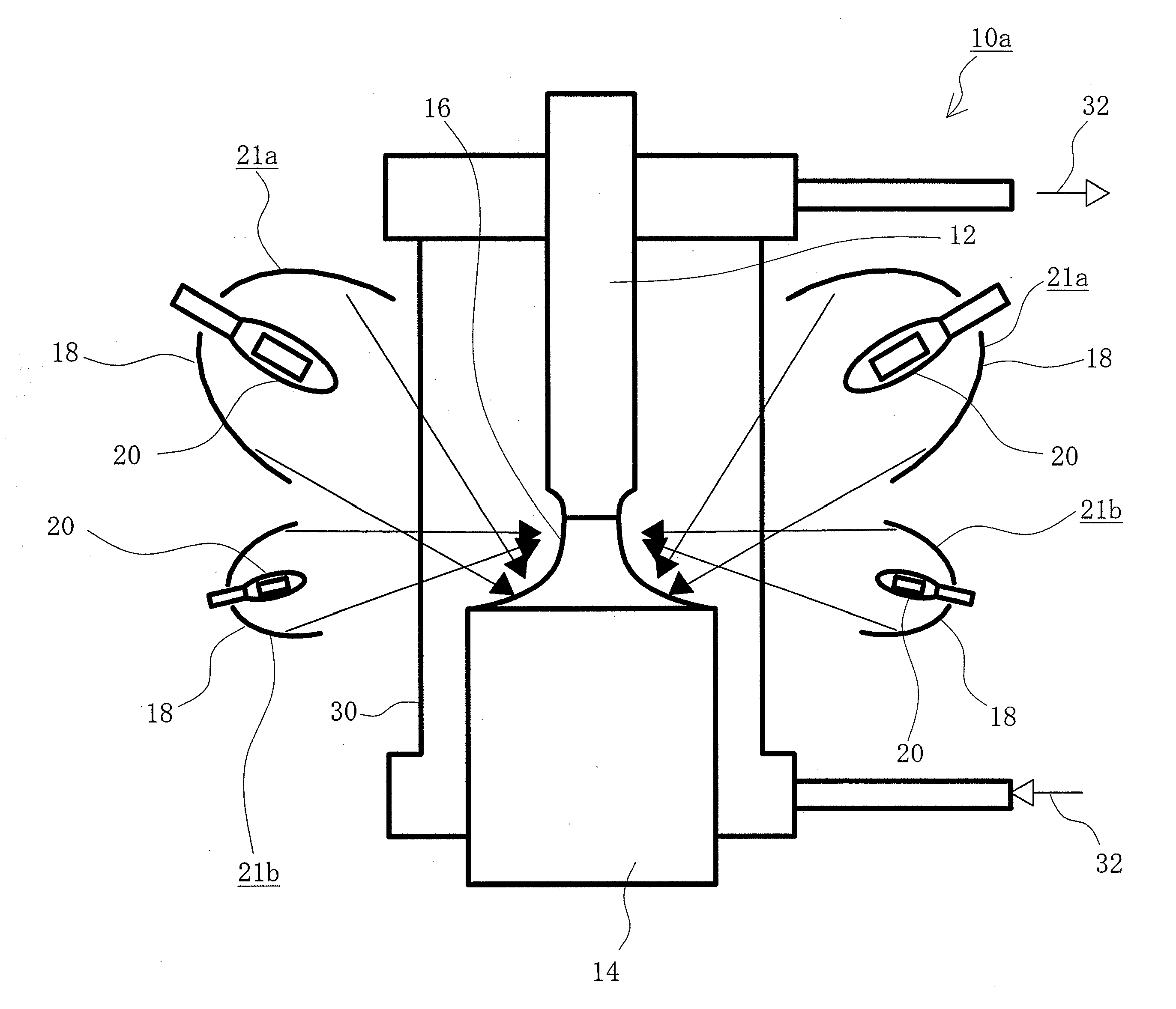
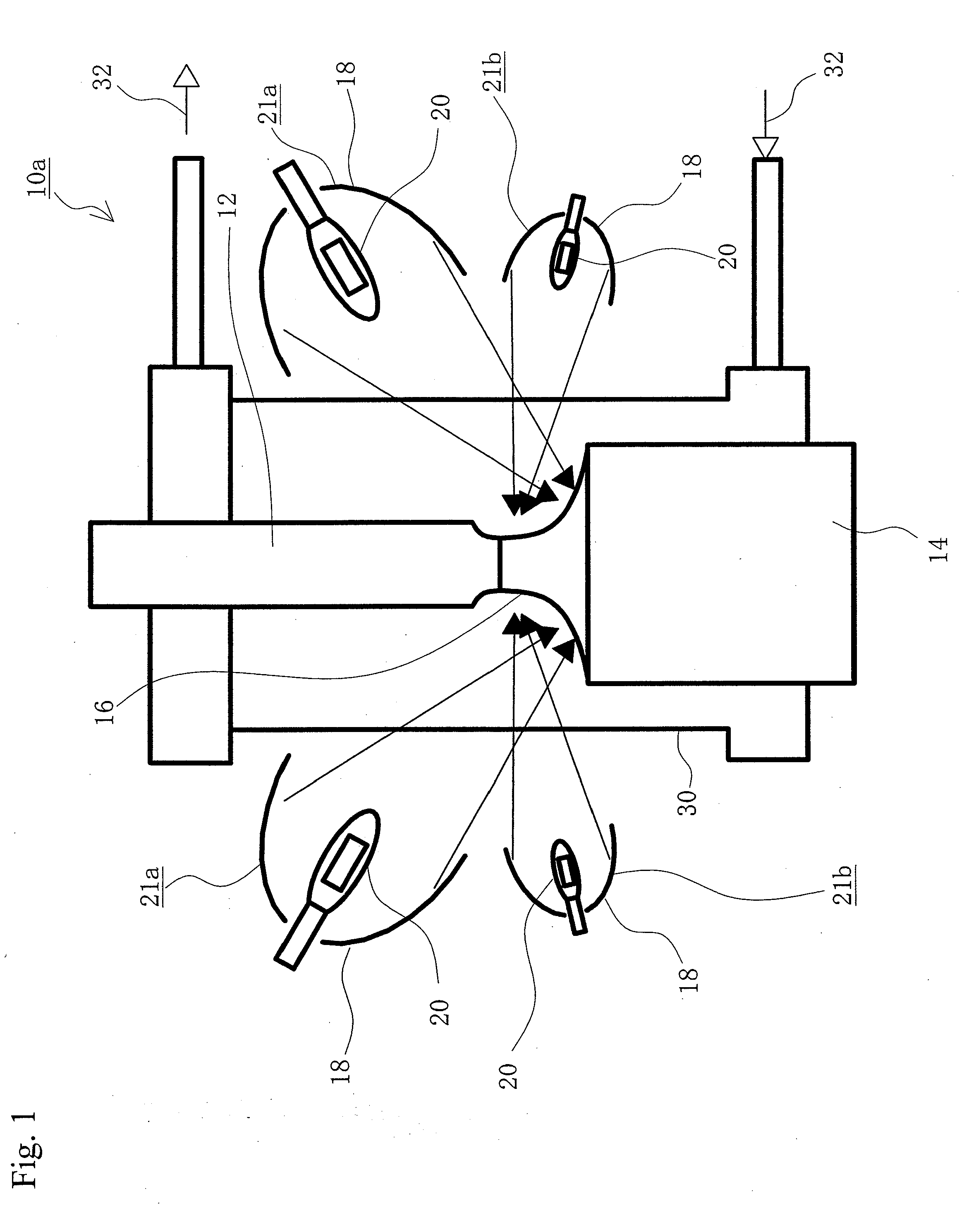
[0189]Eight elliptical mirrors made of a quartz glass were disposed on the horizontal face in such a manner that the elliptical mirrors share one focal point thereof with each other, and a halogen lamp was disposed at the other focal point of each of the elliptical mirrors, whereby eight halogen lamp units were configured. A lamp having an output power of 1000 W in a filament shape having a double helical structure was used for each of the halogen lamps.

[0190]In such a manner that a sample rod is disposed in a vertical direction at the center position of the elliptical mirrors, a sintered sample rod having a diameter of 20 mm was supported from the upper side by a sample rod supporting part, and a seed crystal was supported from the lower side by a growth crystal supporting part.

[0191]Four halogen lamp units of the eight halogen lamp units are disposed at an interval of 90 degrees around the axis of the sample rod and at an angle of 30 degrees in such a manner that the sample in a r...

embodiment 2

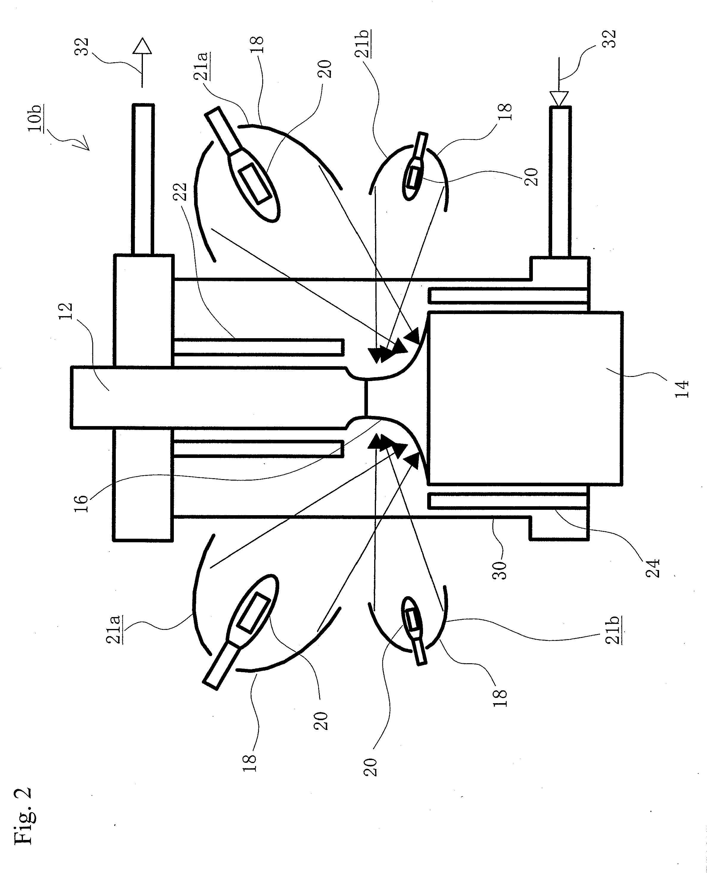
[0197]A single crystal in a rod shape was grown under the conditions equivalent to those of Embodiment 1 except that a sample heating means in a tube shape was disposed in such a manner that a periphery of the sample rod was enclosed, a crystal heating means in a tube shape was disposed in such a manner that a periphery of the seed crystal (the grown crystal) was enclosed, the sample rod was heated by the sample heating means in advance, and the grown crystal of the seed crystal was heated by the crystal heating means in a continuous manner.

[0198]A single crystal that was grown was a single crystal of a high quality having a diameter of 80 mm.

embodiment 3

[0199]A single crystal in a rod shape was grown under the conditions equivalent to those of Embodiment 1 except that a shielding member in a rod shape was disposed around the sample rod and the seed crystal and an irradiation amount of infrared rays that are emitted from the infrared lamp was limited in a growth of a single crystal.

[0200]It was enabled that a single crystal of a high quality having a diameter of 25 mm was grown in a prismatic column shape.


PUM

PropertyMeasurementUnit
diameteraaaaaaaaaa
diameteraaaaaaaaaa
diameteraaaaaaaaaa

Abstract

This invention provides a floating zone melting apparatus in which a sample rod especially having a large diameter can be stably melted with a certainty and the crystal being grown can retain a flat shape at the interface of the solid phase and the liquid phase, whereby a single crystal having a large diameter can be grown.
[Problem] It is an object to provide a floating zone melting apparatus of the infrared concentration heating type in which a sample is set in a sample chamber made of a transparent quartz tube, an atmospheric gas is introduced into the sample chamber, infrared rays emitted from a plurality of infrared ray irradiation means are converged to the sample to heat and melt the sample in this state, thereby obtaining a melt, and the melt is solidified on a seed crystal to grow a single crystal. The plurality of infrared ray irradiation means comprise a plurality of infrared ray irradiation means of the downward irradiation type that emit an infrared ray downward from an oblique upper direction and a plurality of infrared ray irradiation means of the upward irradiation type that emit an infrared ray upward from an oblique lower direction.

Description

TECHNICAL FIELD[0001]The present invention relates to a floating zone melting apparatus of the infrared concentration heating type in which a part of a sample in a rod shape for instance is irradiated with an infrared ray to heat and melt the sample, and the molten sample is solidified on a seed crystal or the like to grow a single crystal in a rod shape.BACKGROUND ART[0002]To produce a single crystal, an infrared lamp unit is prepared in which an infrared lamp such as a halogen lamp and a xenon lamp is disposed at one focal point of an ellipsoidal reflecting mirror (hereafter referred to as an elliptical mirror), infrared rays emitted from the infrared lamp unit are converged to the other focal point, a local heating of a solid sample (a sample in a rod shape for instance) that has been disposed at the location is carried out to melt and deposit the solid sample. The above method is called a floating zone melting method. A great number of floating zone melting apparatuses that adop...

Claims


Application Information

Patent Timeline
Patent Type & Authority Applications(United States)
IPC IPC(8): C30B13/24
CPCY10T117/1024C30B13/24
Inventor SHINDO, ISAMU
Owner CRYSTAL SYST
Why Eureka
Try Eureka