Mechanical chock with cams for climbing and mountaineering

a technology of mechanical chocks and cams, which is applied in the direction of show stands, show hangers, and shelves, can solve problems such as instability, and achieve the effect of optimal anchoring stability

Inactive Publication Date: 2005-07-07
ZEDEL CORP
View PDF14 Cites 6 Cited by
  • Summary
  • Abstract
  • Description
  • Claims
  • Application Information

AI Technical Summary

Benefits of technology

[0007] The object of the invention is to remedy these shortcomings and to achieve a mechanical choc...

Problems solved by technology

Use of this known chock in irregular cracks (FIG. 2) may give rise to problems of ins...

Method used


Image

  • Mechanical chock with cams for climbing and mountaineering
  • Mechanical chock with cams for climbing and mountaineering
  • Mechanical chock with cams for climbing and mountaineering

Examples


Embodiment Construction

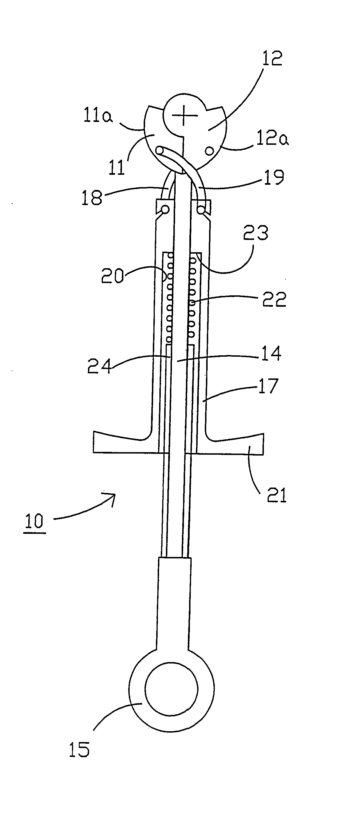
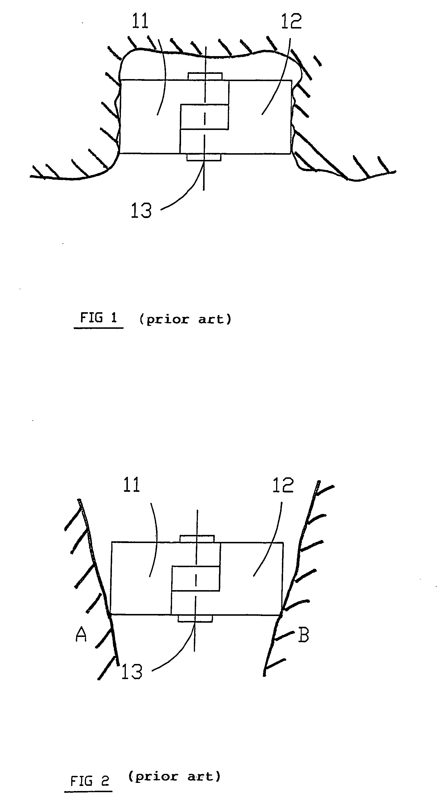
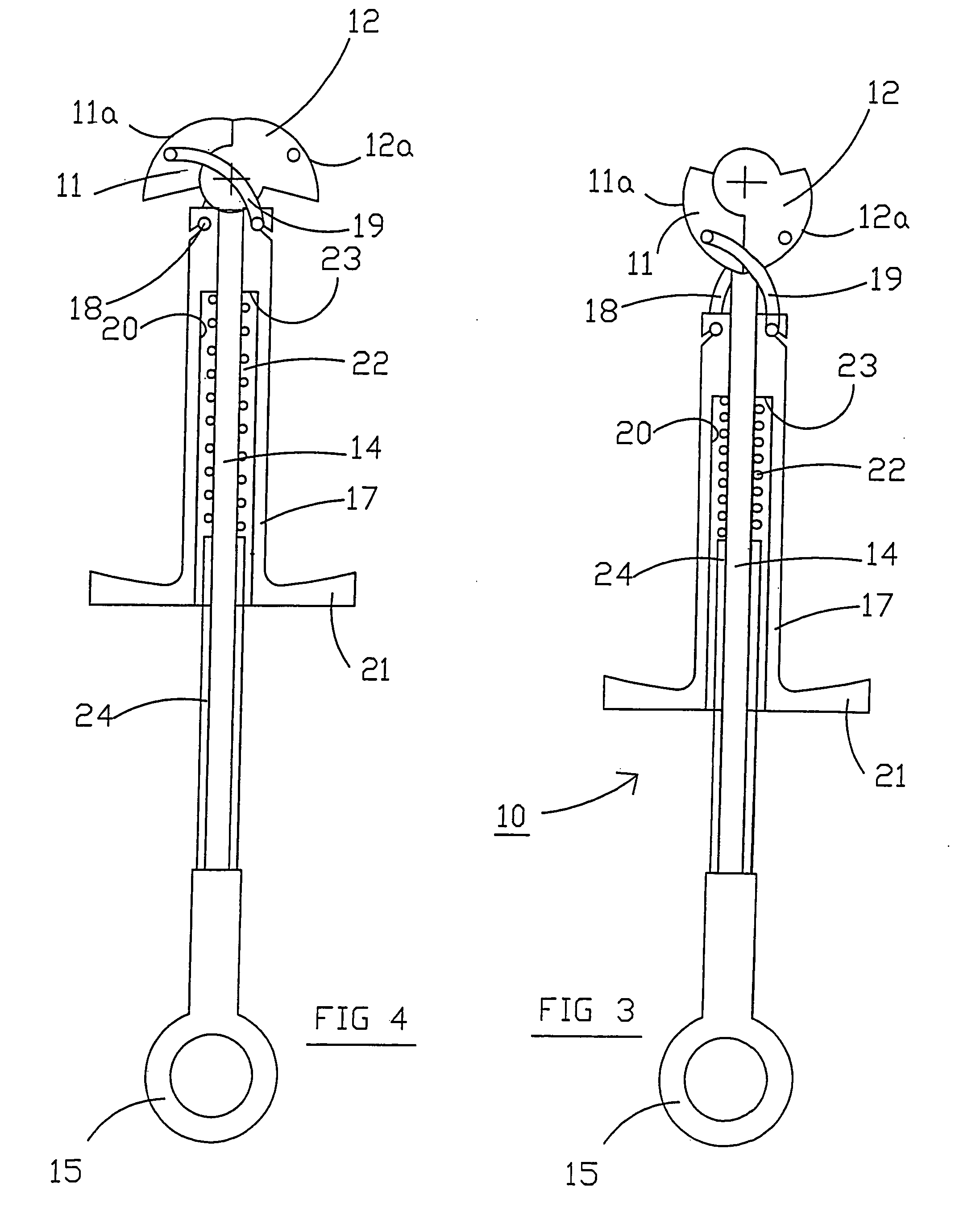
[0017] In FIGS. 3 to 6, a mechanical chock 10 with cams for climbing and mountaineering comprises a pair of anchoring cams 11, 12 mounted in rotation and in opposition on a common support spindle 13.

[0018] The support spindle 13 is fixed and comprises a central body 16 whereto a rope 14 or any other attachment means is attached. The end of the rope 14 is equipped with a ring 15 enabling a karabiner or a belaying rope to be attached.

[0019] The central body 16 of the spindle 13 is equipped with a first half-spindle 13a whereon the first cam 11 is mounted and with a second half-spindle 13b for receiving the second cam 12. The two half-spindles 13a, 13b are coaxial and extend on each side of the central body 16.

[0020] Each cam 11, 12 has a bearing surface 11a, 11b having a logarithmic spiral profile with an angle of about 14°. The bearing surface 11a of the first cam 11 presents a convex face instead of being flat as in the chock of the document WO 02 / 34091. The other bearing surface...


PUM


Abstract

A mechanical chock comprises a pair of anchoring cams mounted in rotation and in opposition on a common support spindle, each cam comprising a bearing surface having a predetermined profile. The bearing surface of the first cam presents a convex face, whereas the bearing surface of the second cam has a concave face, so as to obtain three bearing points or zones in the separated blocking position.

Description

BACKGROUND OF THE INVENTION [0001] The invention relates to a mechanical chock with cams for climbing and mountaineering, and comprising: [0002] at least one pair of anchoring cams mounted in rotation and in opposition on a common support spindle, each cam comprising a bearing surface having a predetermined profile, [0003] an attachment means securedly affixed to a central body of the spindle, which is equipped with a first half-spindle for receiving the first cam and a second half-spindle for receiving the second cam, [0004] and means for operating the cams between a separated blocking position and a retracted releasing position. STATE OF THE ART [0005]FIG. 1 of the application corresponds to the mechanical chock illustrated in the document WO 02 / 34091, which comprises a pair of cams 11, 12 mounted in rotation in opposition on a single spindle 13. Each cam comprises two flat opposite side faces which bound the bearing surface having a curved profile in the form of a spiral. This be...

Claims


Application Information

Patent Timeline
IPC IPC(8): A63B29/02
CPCA63B29/024
Inventor PETZL, PAUL
Owner ZEDEL CORP
Why Eureka
Try Eureka