
Gas generator

a generator and gas technology, applied in the direction of pedestrian/occupant safety arrangement, transportation and packaging, vehicle safety arrangements, etc., can solve the problems of strong shock wave and weak destruction of the second membran

Inactive Publication Date: 2005-07-07
TRW AIRBAG SYST
View PDF18 Cites 27 Cited by
  • Summary
  • Abstract
  • Description
  • Claims
  • Application Information

AI Technical Summary

Benefits of technology

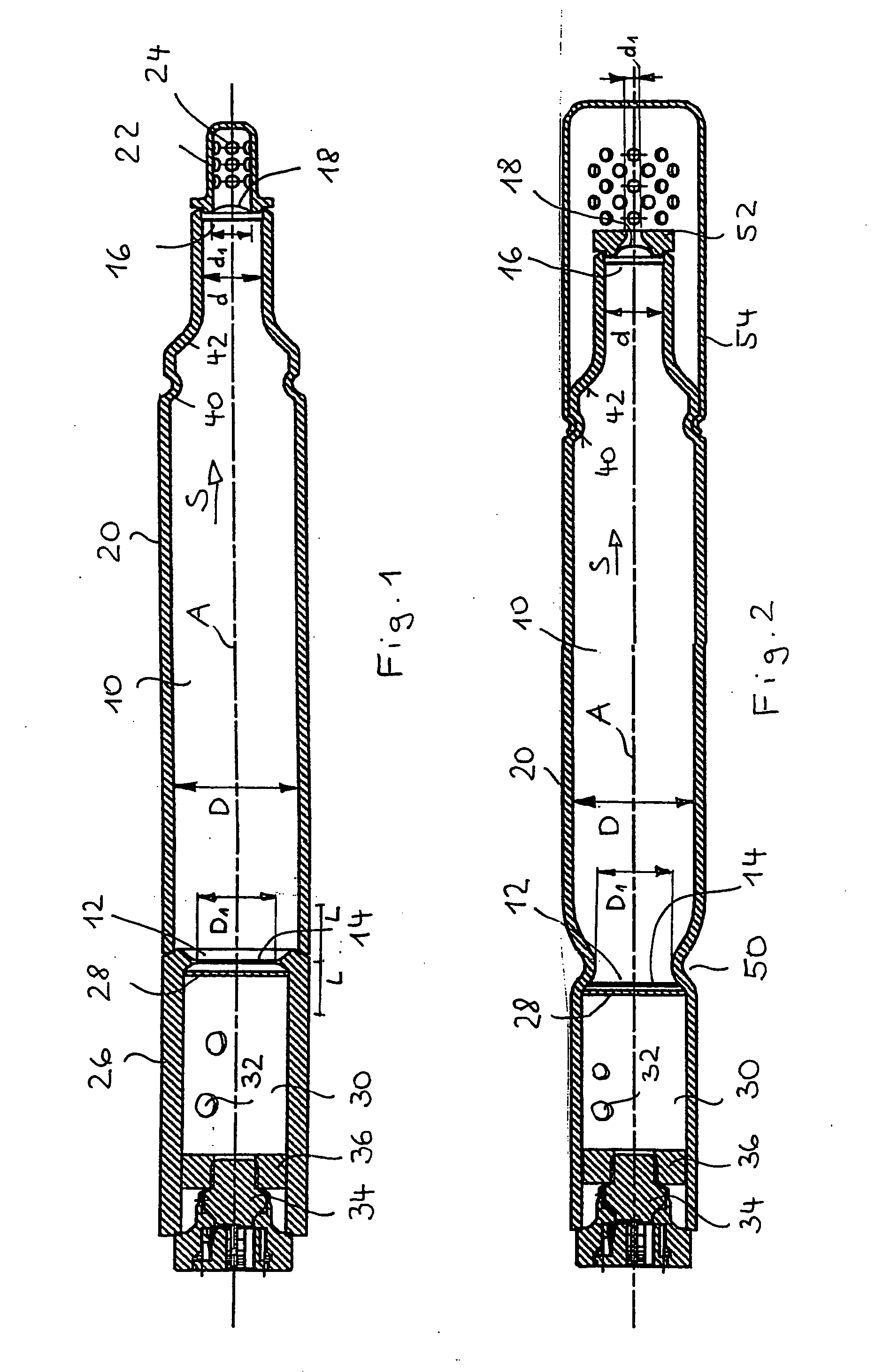
[0006] The present invention further provides a gas generator having a pressure chamber filled with compressed gas, a pyrotechnic igniter arranged outside said pressure chamber, a first membrane provided close to said igniter and closing a first opening of said pressure chamber, a second membrane provided further away from said igniter and closing a second opening of said pressure chamber. The two membranes are destroyed on activation of said igniter. A first opening or opening arrangement associated with the first membrane has a cross-sectional area at least equal in size to that of a second opening or opening arrangement associated with the second membrane, the cross-sectional area of the first opening / opening arrangement, however, being preferably larger than that of the second opening / opening arrangement. When the first opening, exposed by the first igniter, is relatively large, the abrupt drop in pressure between the pressure chamber and the adjoining chamber will likewise be very large, which leads to a very strong shock wave. With an equally large or smaller second opening and with a correspondingly dimensioned second membrane, this relatively strong shock wave can then lead to an easy opening thereof.
[0019] In the very case when a pyrotechnic charge is provided, it can be advantageous to arrange a screen in front of the first membrane, which holds back particles generated on deflagration.

Problems solved by technology

Therefore, however, the pressure wave which runs through the pressure chamber and must lead to the destruction of the second membrane becomes stronger.
When the first opening, exposed by the first igniter, is relatively large, the abrupt drop in pressure between the pressure chamber and the adjoining chamber will likewise be very large, which leads to a very strong shock wave.

Method used


Image

  • Gas generator
  • Gas generator

Examples


Embodiment Construction

[0022] In FIG. 1 an elongated tubular gas generator for inflating a gas bag is shown, which consists of very few individual parts and is distinguished by a good, reproducible opening behavior. The gas generator has a central, elongated, cylindrical pressure chamber 10, which is filled with a compressed gas of helium, a helium / argon mixture or a helium / argon / oxygen mixture at a pressure between 240 and 1500 bar. The pressure chamber 10 has a first, large opening 12 on the left end face, which is closed by a first membrane 14, and also at the opposite end face a second opening 16 of maximum equal size, but preferably smaller, which is closed by a second, smaller membrane 18. The design is made such that the bursting pressure for exposing the first opening 12 is larger than for exposing the second opening 16. The pressure chamber 10 is delimited laterally by a cylindrical outer wall with a cylinder wall 20 configured as a separate part onto which, in the region of the second opening 16...


PUM


Abstract

A gas generator, in particular for vehicle occupant restraint systems, is provided with a pressure chamber (10) filled with compressed gas, a pyrotechnic igniter (34) arranged outside the pressure chamber (10), a first membrane (14) provided close to the igniter (34) and closing a first opening (12) of the pressure chamber (10), and a second membrane (18) provided further away from the igniter (34) and closing a second opening (16) of the pressure chamber. The first membrane (14) is configured such that it tears at a higher bursting pressure than the second membrane (18).

Description

TECHNICAL FIELD [0001] The invention relates to a gas generator, in particular for vehicle occupant restraint systems. BACKGROUND OF THE INVENTION [0002] A gas generator known from WO 01 / 42047 A2 comprises a pressure chamber filled with compressed gas, a pyrotechnic igniter arranged outside said pressure chamber, a first membrane provided close to said igniter and closing a first opening of said pressure chamber, a second membrane provided further away from said igniter and closing a second opening of said pressure chamber. The two membranes are destroyed on activation of said igniter. The second opening, which is closed by the second membrane, is the outflow opening for the gas which is released and flows from this opening into a vehicle occupant restraint system. In accordance with this prior art, the second membrane is destroyed by a shock wave which occurs after the destruction of the first membrane and runs through the pressure chamber. BRIEF SUMMARY OF THE INVENTION [0003] The...

Claims


Application Information

Patent Timeline
IPC IPC(8): B60R21/26B60R21/272
CPCB60R21/272
Inventor BERGMANN, MAXIMILIANHOFMANN, ACHIMHOLZAPFEL, JENSSEIDL, LORENZSEDDIG, MONIKAJUNG, CHRISTIANTENGLER, WOLFGANGSPITZENBERG, ANDREAS
Owner TRW AIRBAG SYST
Learn More