REFERENCE NUMERALS IN THE DRAWINGS
[0025] 10 motorcycle 12 headlight 14 air intake 16 strut 18 fender 20 turn signal 22 radiator opening 24 lower cowling 26 upper cowling 28 windscreen 30 mirror 32 stalk 34 cowling cover 36 headlight opening 38 air intake opening 40 turn signal opening 42 side flap 44 upper tab 46 stalk slot 48 hook tab 50 loop tab 52 outer surface 54 inner surface 56 loop block 58 hook block 60 top wall 62 side wall 64 lower edge 66 cowling side 68 upper corner 70 fender cover 72 strut slot 74 flap 76 hook tab 78 loop tab 80 tube section 82 main panel 84 central portion
DESCRIPTION OF THE INVENTION
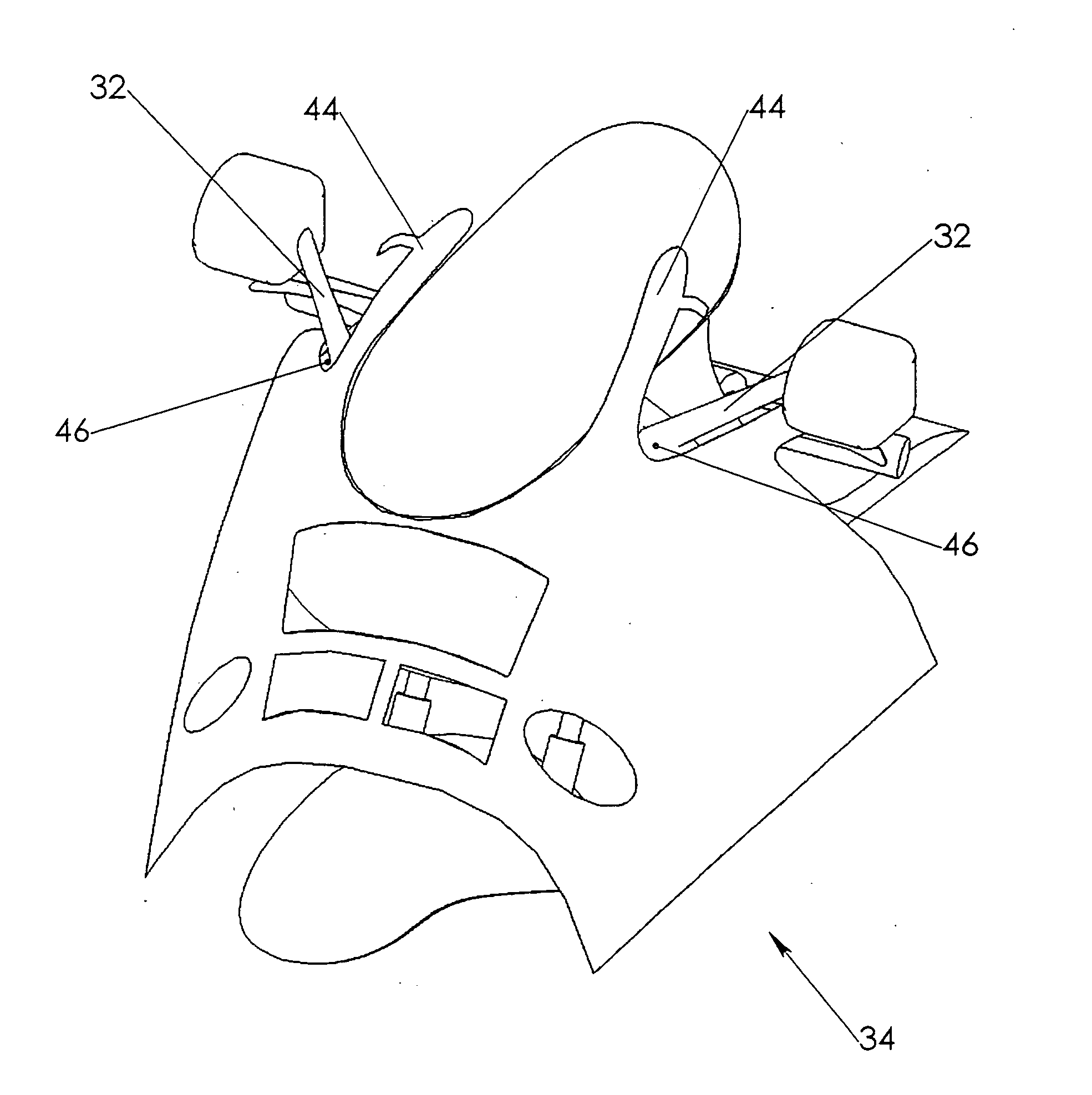
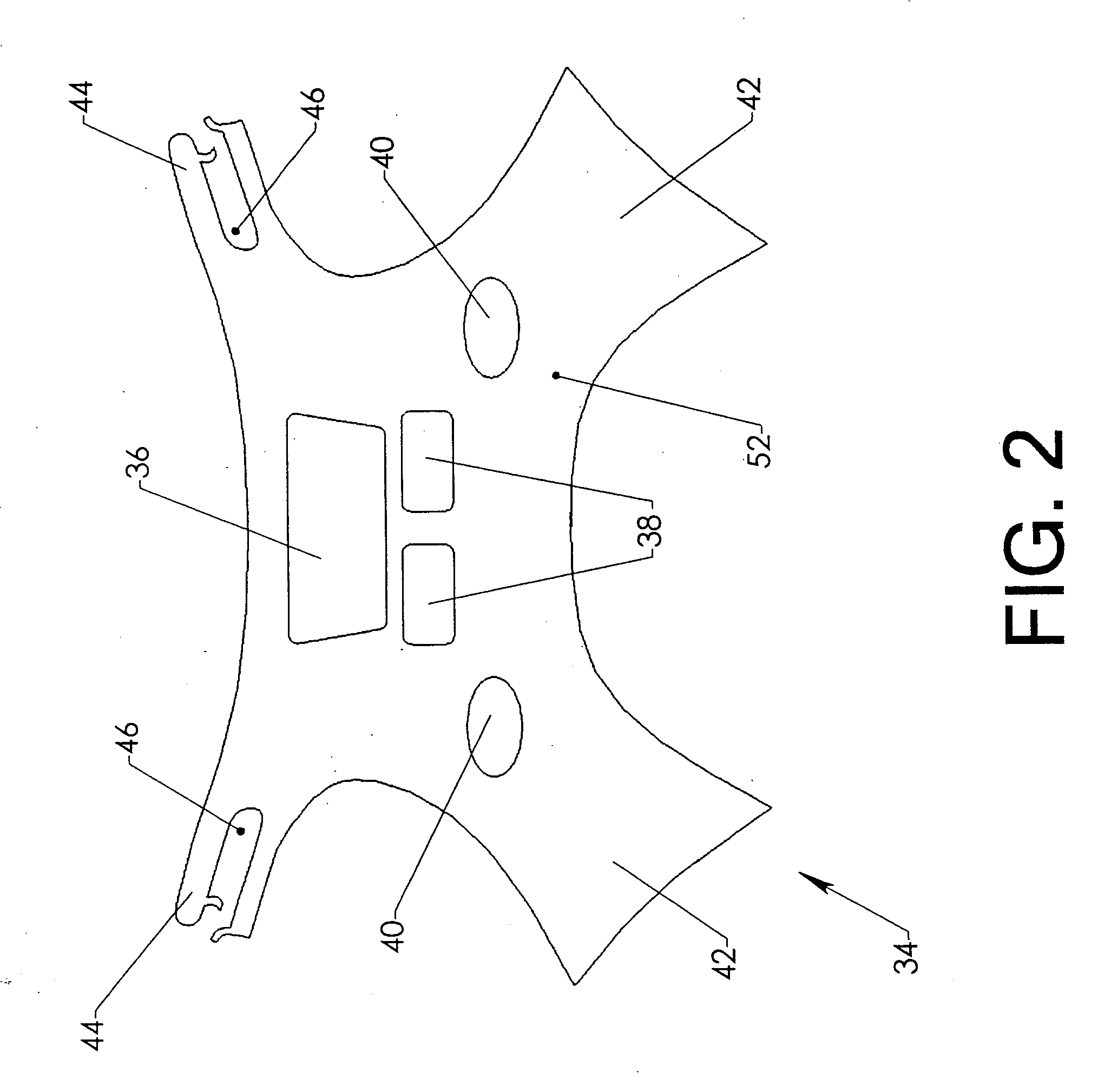
[0026]FIG. 2 shows the present invention laid out in a flattened state. Cowling cover 34 consists primarily of central portion 84 and two attached side flaps 42. The view shows the outward facing side of the device, denoted as outer surface 52. Two turn signal openings 40 are provided near where central portion 84 joins the two side flaps 42.
[0027] Central portion 84 also includes a pair of air intakes 38 and headlight opening 36. Two stalk slots 46 are located near the upper corners of central portion 38. Each stalk slot 46 is bounded by an upper tab 44. FIG. 3 shows a stalk slot 46 in more detail. Loop tab 50 and hook tab 48 are located near the open mouth of stalk slot 46. These hook and loop fasteners (commonly known as VELCRO) can selectively close the open mouth of stalk slot 46. Those skilled in the art will also know that they provide considerable adjustment, the purpose of which will be explained subsequently.
[0028]FIG. 4 shows cowling cover 34 flipped over to reveal inner surface 54 (The surface which customarily faces the motorcycle). The central portion and the two side flaps are bounded on their lower extremes by a continuous lower edge 64. A first loop block 56 is located near the right-hand extreme of lower edge 64 and a second loop block 56 is located near the left-hand extreme. Each loop block is a section of loop-type fastener material which is affixed to the cowling cover, such as by sewing, gluing, or other conventional means.
[0029] A third loop block 56 is located near the lower edge of the central portion. Two more loop blocks 56 are located in the two upper corners 68 of the two side panels. These loop blocks are positioned to mate with hook blocks affixed to the motorcycle. Of course, those skilled in the art will know that the hook and loop blocks can be reversed (the hook blocks on the cowling cover and the loop blocks on the motorcycle). It is also possible to substitute many other types of fasteners such as snaps.
[0030]FIG. 5 shows the first step in the installation of the cowling cover. Cowling cover 34 is draped over the upper cowling as shown. The two stalk slots 46 are opened and the two upper arms 44 are passed over the two stalks 32. The cowling cover is allowed to rest in this position while the next step is performed.
[0031]FIG. 6 shows a detailed view of the area surrounding radiator opening 22. The front wheel, struts, and fender have been removed in this view to aid visualization. The reader will observe that radiator opening 22 is bounded by two side walls 62 and a top wall 60. A hook block 58 is attached to top wall 60 as shown. A hook block 58 is likewise attached to each side wall 62. The blocks can be attached using many methods, but high-strength double-sided tape is particularly effective. In fact, such blocks often come already attached to such tape. Another hook block 58 is affixed to cowling side 66 (A corresponding block is found on the opposite side).
[0032]FIG. 7 shows the next step in the installation process. With the cowling cover draped over the upper cowling, lower edge 64 of central portion 84 is tucked into the radiator opening. The centrally located loop block 56 is then pressed against the hook block 58 located on top wall 60. This holds the lower extreme of the central portion in place.
[0033] Turning now to FIG. 8, the user pulls the cowling cover taut, then locks each stalk slot over each stalk 32 by securing loop tab 50 to hook tab 48 (The adjustable nature of the link between the hook and loop tabs allow the cowling cover to be properly tightened.
[0034]FIG. 9 shows the next step. The user tucks lower edge 64 of the two side flaps into radiator opening 22 and secures them in position by pressing the two loop blocks 56 on the side flaps against the two hook blocks 58 on side walls 62. Finally, the user can secure the two upper corners 68 by pressing the two loop blocks 56 on the two upper corners 68 against the two hook blocks 58 on the two cowling sides 66.
[0035] Using this approach, the leading surfaces of the upper and lower cowling are well protected. The cowling cover can even incorporate mesh panels covering some or all of headlight opening 36, air intake opening 38, or turn signal opening 40.
[0036] However, returning briefly to FIG. 1, the reader will observe that the finished surfaces on fender 18 are not protected by the cowling cover. An additional element is therefore desirable to protect the fender.
[0037]FIG. 10 shows fender cover 70. Main panel 82 opens into a pair of strut slots 72 toward the rear. These are selectively closed by cooperating hook tabs 76 and loop tabs 78. A pair of flaps 74 bound the lower portions of the two strut slots 72. Tube section 80 extends around most of the perimeter of main panel 82.
[0038]FIG. 11 shows a section view through the fender cover in its installed state. Tube section 80 is attached to main panel 82. It is not closed however. It contains a slit along its entire length. The user can pry open this slit and slide it over the exposed edge of fender 18. The tube section, which is made of a pliable material such as rubber, naturally tends to close. It thereby grips the edge of the fender and secures the device in position.
[0039] In FIG. 12, the user has slipped the two strut slots 72 around the two struts 116. In FIG. 13, the user has closed the two strut slots by locking the hook and loop tabs together. The small portions of tube section 80 lying near the rear of the cover are then slipped over the edge of the fender guard and the installation is complete.
[0040]FIG. 14 shows the complete invention installed, with the cowling cover and the fender cover protecting the forward surfaces of the motorcycle.
[0041] Although the preceding description contains significant detail, it should not be viewed as limiting the invention but rather as providing examples of the preferred embodiments. Accordingly, the scope of the invention should be fixed by the following claims rather than by any examples given.