Organic el display and its production method

a technology of electroluminescence and organic el, applied in the direction of discharge tube luminescnet screen, discharge tube/lamp details, organic semiconductor devices, etc., can solve the problems of difficult positioning and difficulty in increasing the opening ratio of pixels, and achieve excellent viewing angle properties and increase production yield

Inactive Publication Date: 2005-07-07
IDEMITSU KOSAN CO LTD
View PDF4 Cites 34 Cited by
  • Summary
  • Abstract
  • Description
  • Claims
  • Application Information

AI Technical Summary

Benefits of technology

[0136] The similar advantageous effects can be obtained by applying a polymer containing an ultraviolet-ray absorber (not shown) to the top surface of a sealing layer.
[0137] There are exemplified polymers containing an ultraviolet-ray absorber such as triazole type absorbers and triazine type absorbers. The preferred film thickness is from about 0.5 to about 5 μm.
[0138] Thereafter a flattening layer 8 is formed and a sealing substrate 5 is adhered in the same way as the first embodiment to produce an organic EL display as shown in FIG. 7.
[0139] The precise positioning of the supporting substrate 1 and sealing substrate 5 is not required at the time of adhering them to each other since the coloring layers 4 are formed at precise positions by photolithography on the supporting substrate 1 side. Thus even if the display is of top emission type, its production yield can be increased.
[0140] Further the display has excellent viewing angle properties since it does not have a flattening layer between the coloring layer 4 and organic EL device 2.
[0141] Although some structures of the invention have been explained in the above embodiments, various changes may be made. For example, although a display provided with TFTs has been described in the above embodiments, the invention can be preferably applied to a display with no TFTs.

Problems solved by technology

Further, in the bottom emission type, light cannot be taken out from parts where TFTs 6 are formed so that it is difficult to increase the opening ratio of pixels.
Such positioning is difficult so that the organic EL display of top emission type has a production yield lower than that of bottom emission type.

Method used


Image

  • Organic el display and its production method
  • Organic el display and its production method
  • Organic el display and its production method

Examples


first embodiment

[0065] Referring to the drawings, an organic EL display and its production method according to a first embodiment of the invention will be described hereinafter.

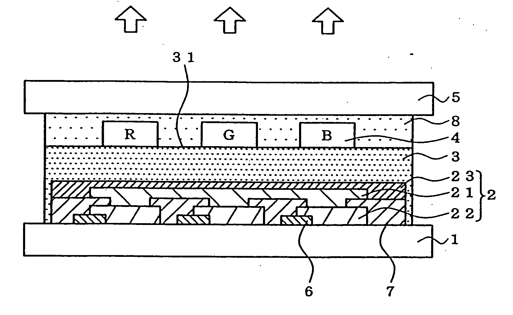
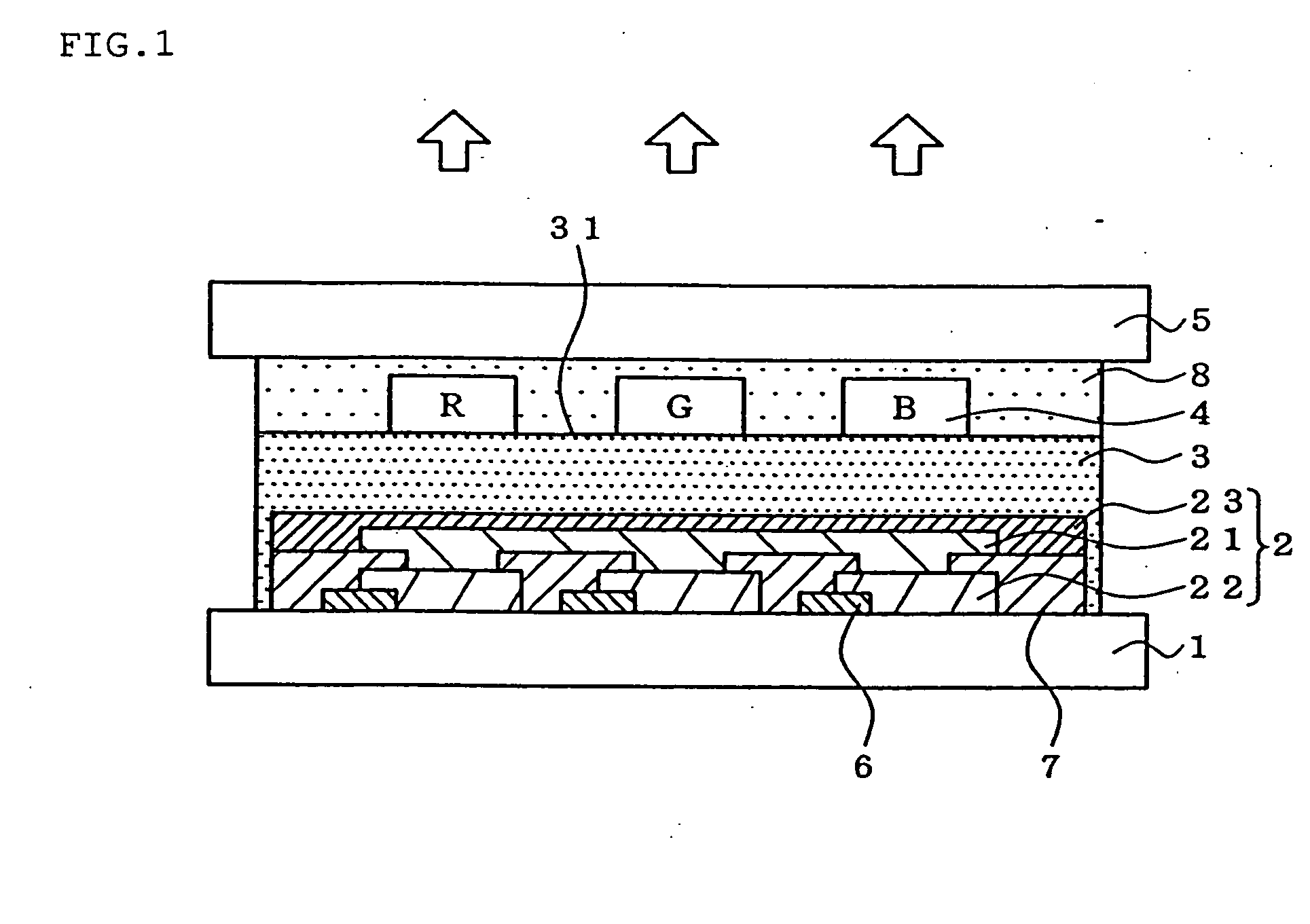
[0066]FIG. 1 is a diagram for explaining the structure of the organic EL display of the first embodiment.

[0067] As shown in this figure, in the organic EL display, TFTs 6 and under electrode 22 are formed on a supporting substrate 1, and an insulator 7, organic luminescent medium 21, upper electrode 23, sealing layer 3, coloring layer 4 and flattening layer 8 are laminated thereon in this order, a sealing substrate 5 being on the uppermost surface. The under electrode 22, organic luminescent medium 21 and upper electrode 23 constitute an organic EL device 2. Arrows show the direction in which light is taken out.

[0068] If a voltage is applied between the under and upper electrodes 22, 23, the organic luminescent medium 21 held by them emits light and the light passes via the sealing layer 3 to the coloring layer 4. The col...

second embodiment

[0085] An organic EL display and its production method according to a second embodiment of the invention will be described with reference to drawings.

[0086]FIG. 3 is a diagram for explaining the structure of the organic EL display of the second embodiment. The same members as the first embodiment are denoted by the same reference numerals and their detail explanation is omitted.

[0087] In this display, numeral 20 denotes an opening area and numeral 30 denotes a non-opening area. In only the opening area 20, an organic luminescent medium 21 emits light since the medium 21 is sandwiched between under and upper electrodes 22, 23. The light is taken out to the outside via a coloring layer 4. That is, light is taken out in the opening area 20 but light is not taken out in the non-opening area 30.

[0088] In the second embodiment, part of the surface 31 is not ink-repellent but concave parts 32 are formed in at least part of the opening area 20 on the top surface 31 of a sealing layer ins...

third embodiment

[0110] An organic EL display and its production method according to a third embodiment of the invention will be described with reference to drawings.

[0111]FIG. 5 is a diagram for explaining the structure of the organic EL display of the third embodiment. The same members as the first embodiment are denoted by the same reference numerals and their detail explanation is omitted.

[0112] In the third embodiment, part of the surface 31 of the sealing layer is not ink-repellent but an ink-receiving layer 10 is provided on a sealing layer 3 instead. Coloring layers 4 are provided at certain positions of the ink-receiving layer.

[0113] The ink-receiving layer is made of an ink-permeable resin and formed by printing, spin coating or applying. The layer has a thickness of about 0.5 μm to about 20 μm. Preferred resins include polyvinyl alcohols, celluloses and acrylate resins.

[0114] Next referring to FIG. 6, the method of producing the organic EL display according to the third embodiment wil...


PUM


Abstract

An organic EL device (2) and an sealing layer (3) are formed on a supporting substrate (1). The top surface (31) of the sealing layer is made repellent to ink. Ink is printed by an ink jet method to form a coloring layer (4). A flattening layer (8) is formed, and thereafter a sealing substrate (5) is bonded. Since the coloring layer (4) is not previously formed on the sealing substrate (5), no precise positioning for bonding the sealing substrate (5) to the supporting substrate (1) is needed. The viewing angle properties are enhanced since the distance between the organic EL device (2) and the coloring layer (4) can be small. Thus, there are provided an organic EL display of top emission type with a high production yield and excellent viewing angle properties and its production method.

Description

TECHNICAL FIELD [0001] This invention relates to an organic electroluminescence (EL) display and its production method. More specifically, the invention relates to an organic EL display of top emission type where light is taken out from a sealing substrate side, and its production method. BACKGROUND ART [0002] An organic EL display is constructed from organic EL devices with an organic luminescent medium containing organic luminescent molecules held between opposite electrodes. If a voltage is applied across the electrodes, electrons injected from an electrode recombine with holes from another electrode in an organic emitting layer of the organic luminescent medium. The organic luminescent molecules change to the exited state by the recombination energy and then return to the base state. At this time energy is discharged. The organic EL device emits light by taking out this energy as light. [0003] An organic EL display constructed from organic EL devices of such luminescent principl...

Claims


Application Information

Patent Timeline
Patent Type & Authority Applications(United States)
IPC IPC(8): H01L27/32H01L51/52
CPCH01L27/322H01L2251/5315H01L51/5237H10K59/38H10K50/841H10K50/844H10K2102/3026H05B33/04H05B33/14H05B33/12H05B33/10
Inventor KUMA, HITOSHIEIDA, MITSURUHOSOKAWA, CHISHIO
Owner IDEMITSU KOSAN CO LTD
Why Eureka
Try Eureka